
Single-layer chip type laser radar device and method of manufacturing same

A laser radar, single-layer technology, applied in the re-radiation of electromagnetic waves, the use of re-radiation, measurement devices, etc., can solve the problem that the yield cannot be effectively controlled, the volume of the laser radar is reduced, and the production and use are inconvenient. and other problems, to achieve the effect of reducing cost and installation difficulty, reducing the number of lenses, and reducing energy consumption

Pending Publication Date: 2020-09-08
NINGBO SUNNY AUTOMOTIVE OPTECH
View PDF10 Cites 0 Cited by
  • Summary
  • Abstract
  • Description
  • Claims
  • Application Information

AI Technical Summary

Problems solved by technology

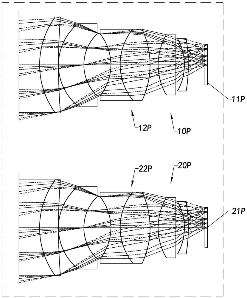
It is impossible to reduce the overall volume of the laser radar without solving the problem in terms of the volume of the transmitting lens 12P and the receiving lens 22P
[0005] In addition, complex lens sets will bring high cost investment in both R&D and manufacturing
The yield rate of the overall equipment cannot be effectively controlled
Moreover, when the transmitting end 10P and the receiving end 20P are manufactured and installed separately, the relative position and matching degree require extra effort, which is inconvenient for production and use.

Method used


Image

  • Single-layer chip type laser radar device and method of manufacturing same
  • Single-layer chip type laser radar device and method of manufacturing same
  • Single-layer chip type laser radar device and method of manufacturing same

Examples


Embodiment Construction

[0087] The following description serves to disclose the present invention to enable those skilled in the art to carry out the present invention. The preferred embodiments described below are only examples, and those skilled in the art can devise other obvious variations. The basic principles of the present invention defined in the following description can be applied to other embodiments, variations, improvements, equivalents and other technical solutions without departing from the spirit and scope of the present invention.

[0088] Those skilled in the art should understand that in the disclosure of the present invention, the terms "vertical", "transverse", "upper", "lower", "front", "rear", "left", "right", " The orientation or positional relationship indicated by "vertical", "horizontal", "top", "bottom", "inner", "outer", etc. is based on the orientation or positional relationship shown in the drawings, which are only for the convenience of describing the present invention...


PUM


Abstract

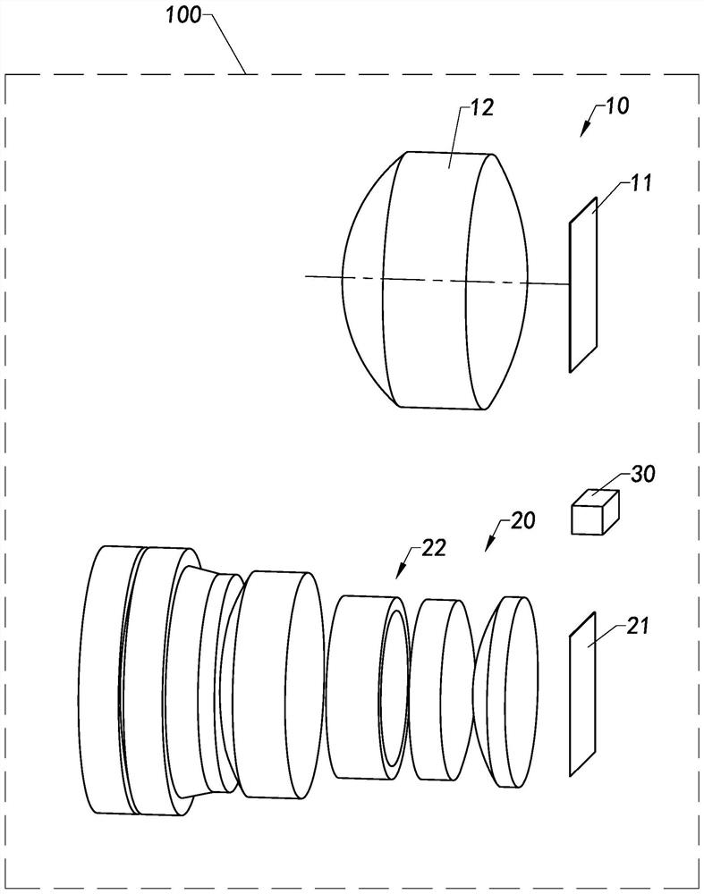
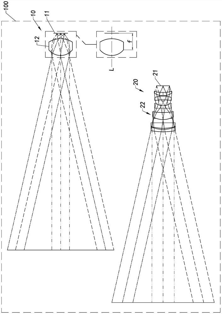
The invention provides a single-layer chip type laser radar device. The device comprises a transmitting module, a receiving module and a processing module, wherein the transmitting module provides laser light to a preset range; the receiving module senses reflected laser rays from a preset range to be measured and calculated by the processing module; the transmitting module comprises a light source device and a transmitting lens, and the transmitting lens is of a single-layer type, so that the distance between the light source device and the transmitting lens determines the length of the single-layer chip type laser radar equipment. In addition, the invention provides a method of manufacturing the single-layer chip type laser radar device.

Description

technical field [0001] The invention relates to the fields of radar detection and laser radar, in particular to a single-layer laser radar device and a manufacturing and assembling method. Background technique [0002] LiDAR uses laser emission and reflection to detect target objects within the range. The efficiency of simple and common laser emission and reception is very low, and a complex optical system is needed to supplement the functions of emission and reception. Moreover, usually both ends need to be strengthened at the same time, otherwise it is easy to cause inaccurate judgment in post-processing. If the requirements for the emission and reception of light are not met, then no matter how good the algorithm processing is, the detection result cannot be accurately judged. [0003] Existing lidar devices such as figure 1 As shown, it mainly includes a transmitting end 10P and a receiving end 20P. The emitting end 10P further includes a laser light source 11P and a...

Claims


Application Information

Patent Timeline
Patent Type & Authority Applications(China)
IPC IPC(8): G01S7/481G01S17/02
CPCG01S7/481G01S7/4814G01S7/4816G01S17/02
Inventor 张俊明徐超杨佳曹艳亭
Owner NINGBO SUNNY AUTOMOTIVE OPTECH
Learn More