Nuclear-grade limit switch for monitoring opening and closing states of nuclear-grade valve
A technology of opening and closing state and limit switch, which is applied in the direction of electric switches, electrical components, circuits, etc., can solve the requirements of nuclear-grade valves that cannot be used, electronic components that are not resistant to radiation environments, and poor reliability of reed switches and other problems, to achieve the effect of completely sealed structure, light weight and fast switching action.
- Summary
- Abstract
- Description
- Claims
- Application Information
AI Technical Summary
Problems solved by technology
Method used
Image
Examples
Embodiment 1
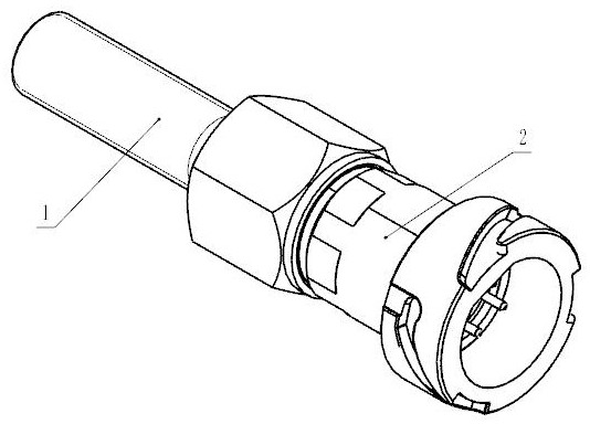
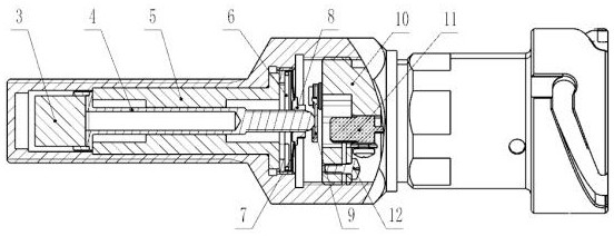
[0027] A nuclear level limit switch that monitors the opening and closing status of nuclear level valves, such as figure 1 , figure 2 As shown, it includes a socket 2, a housing 1, and a switch magnet 3, a central rod 4, a guide sleeve 5, a bouncing diaphragm 7, a spring leaf 9, and a micro switch 11 arranged inside the housing 1 from left to right; The guide sleeve 5 is coaxially assembled inside the housing 1, the central rod 4 is slidably sleeved in the guide sleeve 5, the right end of the central rod 4 is provided with a bouncing diaphragm 7, and the switch magnet 3 is connected with the bouncing diaphragm 7 through the center rod 4, the right side of the center rod 4 is provided with a spring piece 9, and the inside of the housing 1 is correspondingly provided with a micro switch 11, and the spring piece 9 connects the center rod 4 The position change of is transmitted to the micro switch 11, and the micro switch 11 is connected with the socket 2.
[0028] Such as fig...
Embodiment 2
[0031] This embodiment is optimized on the basis of embodiment 1, such as figure 2 As shown, it also includes a support ring 6 and a fixed nut 8; the right end of the center rod 4 is provided with a support ring 6, the spring diaphragm 7 is arranged on the support ring 6, and the right end of the center rod 4 is also A fixing nut 8 is provided to fix the position of the bouncing diaphragm 7 .
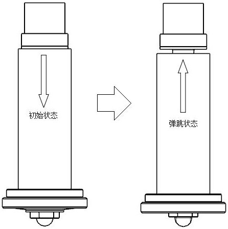
[0032] Such as image 3 As shown, when the nuclear-level limit switch is working, the system has two working states. When it is in the initial state, the measured target is far away from the limit switch, and the bouncing diaphragm 7 is in the non-bouncing state. When it is in the bouncing state , at this time the measured target is close to the limit switch, and the bouncing diaphragm 7 is in a bouncing state.
[0033] Other parts of this embodiment are the same as those of Embodiment 1, so details are not repeated here.
Embodiment 3
[0035] This embodiment is optimized on the basis of Embodiment 1 or 2, and the switch magnet 3 is connected to the central rod 4 by magnetic force. The switch magnet 3 is a permanent magnet, and the permanent magnet and the bouncing diaphragm 7 are sensitive elements for sensing the magnetic force of the measured target. The central rod 4 connects the permanent magnet with the bouncing diaphragm 7 and plays the role of transmitting the displacement, and outputs the electrical signal of the switching value through the micro switch 11. Compared with the general limit switch, the nuclear level limit switch of the present invention adopts In order to simplify the design, there are fewer components, simpler structure, lighter weight and higher reliability. The micro switch 11 is fixedly installed inside the casing 1 through the mounting base 10 and the screw 12 .
[0036] Such as Figure 4 As shown, the housing 1 and the socket 2 form a sealed cavity by vacuum electron beam weldi...
PUM
 Abstract
Description
Claims
Application Information
 - R&D
- Intellectual Property
- Life Sciences
- Materials
- Tech Scout
- Unparalleled Data Quality
- Higher Quality Content
- 60% Fewer Hallucinations
Browse by: Latest US Patents, China's latest patents, Technical Efficacy Thesaurus, Application Domain, Technology Topic, Popular Technical Reports.
© 2025 PatSnap. All rights reserved.Legal|Privacy policy|Modern Slavery Act Transparency Statement|Sitemap|About US| Contact US: help@patsnap.com


