Complex ground wire relation conversion circuit

A conversion circuit and complex ground technology, applied in the direction of amplifier protection circuit layout, etc., can solve problems such as complex circuits and large circuit volumes, and achieve the effects of high signal accuracy, strong anti-interference, and increased distance

Active Publication Date: 2020-09-08
XIAN MICROELECTRONICS TECH INST
View PDF3 Cites 0 Cited by
  • Summary
  • Abstract
  • Description
  • Claims
  • Application Information

AI Technical Summary

Problems solved by technology

The isolation method usually used is an isolation transformer or an isolation chip...

Method used


Image

  • Complex ground wire relation conversion circuit

Examples


Embodiment Construction

[0021] The present invention is described in further detail below in conjunction with accompanying drawing:

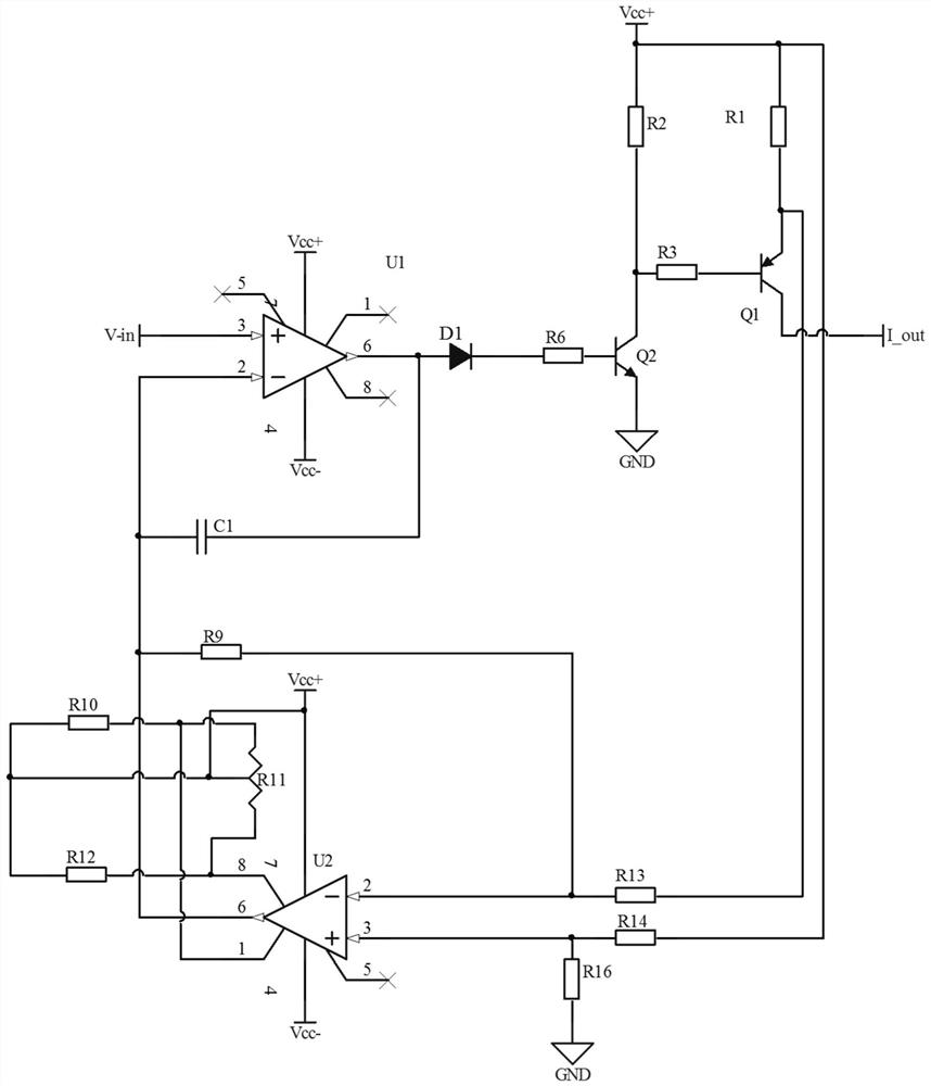
[0022] Such as figure 1 As shown, it is the complex ground line relationship conversion circuit of the present invention, including operational amplifier U1, transistor Q1, transistor Q2 and differential sampling circuit.

[0023] The operational amplifier U1 works in the linear region. The non-inverting input terminal receives the external voltage signal and compares the voltage signal fed back from the inverting input terminal to output a certain level signal to the subsequent stage. The non-inverting input terminal of the operational amplifier U1 is connected to the voltage input. The output terminal of the operational amplifier U1 is connected to the base of the transistor Q2, the emitter of the transistor Q2 is grounded, the collector of the transistor Q2 is connected to the base of the transistor Q1, and connected to Vcc+ through the resistor R2, the collector of...


PUM


Abstract

The invention discloses a complex ground wire relation conversion circuit. The in-phase input end of an operational amplifier U1 is connected with voltage input; the output end of the operational amplifier U1 is connected with the base electrode of a triode Q2; the emitter of the triode Q2 is grounded; the collector electrode of the triode Q2 is connected with the Vcc + and the base electrode of atriode Q1; the collector of the triode Q1 is connected with the current output; the emitting electrode of the triode Q1 is connected with Vcc +; the Vcc + and the emitting electrode of the triode Q1are connected with the input end of the differential sampling circuit; the output end of the differential sampling circuit is connected with the first end of a resistor R10, the two ends of a resistorR11, the first end of a resistor R12 and the inverted input end of the operational amplifier U1, the resistor R10, the resistor R11 and the resistor R12 are connected in series, and one end of the resistor R11 is connected between the resistor R10 and the resistor R12. The conversion of the ground wire relation in a complex system becomes simple and reliable, and the converted signal is extremelyhigh in precision and extremely high in anti-interference performance.

Description

technical field [0001] The invention belongs to the field of ground wire relationship conversion and relates to a complicated ground wire relationship conversion circuit. Background technique [0002] At this stage, circuit isolation is used to convert the ground wire relationship. The main purpose of circuit isolation is to cut off the path of noise interference by isolating components, so as to achieve the effect of suppressing noise interference. After adopting the measures of circuit isolation, most circuits can achieve a good effect of suppressing noise, so that the equipment meets the requirements of electromagnetic compatibility. The isolation methods usually used are isolation transformers or isolation chips such as optocouplers. The circuit is relatively large and complex. Contents of the invention [0003] The purpose of the present invention is to overcome the above-mentioned shortcomings of the prior art, and provide a complex ground wire relationship conversi...

Claims


Application Information

Patent Timeline
IPC IPC(8): H03F1/52
CPCH03F1/52
Inventor 范喆张宏科
Owner XIAN MICROELECTRONICS TECH INST
Why Eureka
Try Eureka