Portable engineering drawing folding machine
A kind of engineering drawing and portable technology, which is applied in the field of portable engineering drawing folding machine, can solve the problems of increasing the labor intensity of the staff, troubles of drawing folding work, inconvenient operation and maintenance, etc., and achieves small equipment occupation space, strong practicability, and easy operation Effect
- Summary
- Abstract
- Description
- Claims
- Application Information
AI Technical Summary
Problems solved by technology
Method used
Image

Examples
Embodiment 1
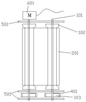
[0022] see figure 1 In Embodiment 1 of the present invention, the portable engineering drawing folding machine includes four parts: a frame 501, a motor 601, a transmission device, and an indentation device, wherein the transmission device includes a transmission shaft 101, a transmission drum 102, a gear 103, and an upper conveyor belt 201 , the lower conveyor belt 301, the gear teeth 401, and the indentation device includes an upper belt short-side protrusion 202, an upper belt short-side groove 203, an upper belt long-side protrusion 204, an upper belt long-side groove 205, and a lower belt short-side protrusion Lifting 303, lower belt short side groove 302, lower belt long side protrusion 305, lower belt long side groove 304, it is characterized in that four identical drive rollers 102 are divided into upper and lower groups, symmetrically arranged on the frame 501, four drive rollers 102 are parallel in pairs, upper conveyor belts 201 are set on the two drive rollers 102 ...
Embodiment 2
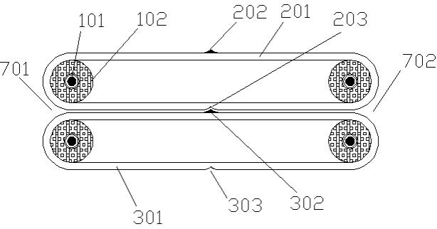
[0029] see figure 2 , this figure is a schematic diagram of the expansion of the conveyor belt 201 on the portable engineering drawing folding machine. In the figure, the upper belt short side protrusions 202, the upper belt short side grooves 203, the upper belt long side protrusions 204, and the upper belt are arranged on the upper conveyor belt 201. The position and distance of the groove 205 on the long side are clear at a glance. The bonding side I 206 and the bonding side II 207 belong to the same side in the actual operation process. After the bonding side I 206 and the bonding side II 207 are bonded, the upper conveyor belt 201 will form an Contiguous barrel conveyors.
Embodiment 3
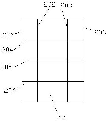
[0031] see image 3 , this figure is a schematic diagram of the expansion of the lower conveyor belt 301 of the portable engineering drawing folding machine. In the figure, the lower belt short-side protrusions 203, the lower belt short-side grooves 302, the lower belt long-side protrusions 305, and the lower belt are arranged on the upper conveyor belt 301. The position and distance of the long side groove 304 are clear at a glance. The bonding side I 206 and the bonding side II 207 belong to the same side in the actual operation process. After the bonding side III 306 and the bonding side IV 307 are bonded, the lower conveyor belt 301 will form a End-to-end barrel conveyor belts.
PUM
 Abstract
Description
Claims
Application Information