Spinning machine discharging mechanism with tailoring structure

A discharge mechanism and textile machine technology, applied in textile, textile and papermaking, mechanical cleaning, etc., can solve problems affecting textile, cumbersome operation, dust contamination, etc., reduce the probability of wrinkles, ensure production quality, and have good use effects Effect

Active Publication Date: 2020-09-11
嘉兴如运建筑科技有限公司
View PDF8 Cites 9 Cited by
  • Summary
  • Abstract
  • Description
  • Claims
  • Application Information

AI Technical Summary

Problems solved by technology

[0003] In textile production, it is necessary to use the discharge mechanism to continuously feed the textile machine. In the traditional discharge mechanism, the fabric is wound on the discharge roller. During the discharge process, the fabric will be wrinkled and affect the The next step of weaving will result in poor quality of textile output, and the cloth will be contaminated with dust during the long-term storage process. The existing discharging mechanism cannot remove the dust on the cloth, which has certain limitations. In addition, the existing discharging mechanism The cutting of the cloth needs to be cut manually, and the operation is cumbersome, which leads to the fact that the existing discharging mechanism cannot meet the needs of use well

Method used


Image

  • Spinning machine discharging mechanism with tailoring structure
  • Spinning machine discharging mechanism with tailoring structure
  • Spinning machine discharging mechanism with tailoring structure

Examples


Embodiment Construction

[0028] The following will clearly and completely describe the technical solutions in the embodiments of the present invention with reference to the accompanying drawings in the embodiments of the present invention. Obviously, the described embodiments are only some, not all, embodiments of the present invention.

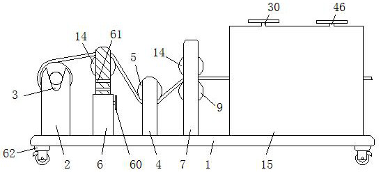
[0029] refer to Figure 1-7 , a textile machine discharge mechanism with a cutting structure, including a base 1, the four corners of the lower end of the base 1 are respectively connected with casters 62, and the casters 62 are brake wheels, which enhances the mobility of the device, and the casters 62 can be braked and locked. Avoid sliding of the device during operation.

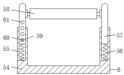
[0030]The upper end of the base 1 is fixedly connected with two pillars 2, a tensioning device 6, a first frame 4, a conveying device 7 and a box body 15 in order from left to right, and the tensioning device 6 includes a fourth frame fixedly connected with the base 1 54, the upper end of the f...


PUM


Abstract

The invention relates to the technical field of spinning, in particular to a spinning machine discharging mechanism with a tailoring structure. A base is included. The upper end of the base is sequentially fixedly connected with two support columns, a tensioning device, a first framework, a conveying device and a box from left to right. The upper portion and the lower portion of the left side of the inner wall of the box are symmetrically fixedly connected with second connecting plates. The second connecting plates are provided with through grooves. Movable rods are movably connected in the through grooves. The opposite sides of the two movable rods are fixedly connected with movable plates. Rotation shafts are symmetrically and rotationally connected between the left portions of the frontside and the rear side of the inner wall of the box. Worm gears are fixedly in cup joint to the rear sides of the outer portions of the rotation shafts. Worms engaged with the worm gears are rotationally connected between the upper end and the lower end of the inner wall of the box. By means of the spinning machine discharging mechanism, wrinkles of cloth in the conveying process can be avoided,dust on the cloth is removed, practicability and functionality of the device are greatly improved, and the spinning machine discharging mechanism is worthy of popularization and usage.

Description

technical field [0001] The invention relates to the technical field of textiles, in particular to a textile machine discharge mechanism with a cutting structure. Background technique [0002] Textile machines are also called spinning machines, looms, cotton spinning machines, etc. Ancient textile machines are looms driven by manpower, such as spinning pendants, spinning wheels, spindles, and pedal looms, as well as modern mechanical looms, modern Numerical control automatic looms, etc., the development of ancient and modern textile processes and equipment are designed in response to textile raw materials. Therefore, raw materials play an important role in textile technology. [0003] In textile production, it is necessary to use the discharge mechanism to continuously feed the textile machine. In the traditional discharge mechanism, the fabric is wound on the discharge roller. During the discharge process, the fabric will be wrinkled and affect the The next step of weaving ...

Claims


Application Information

Patent Timeline
Patent Type & Authority Applications(China)
IPC IPC(8): D03J1/08D03J1/06D06G1/00B65H23/26
CPCD03J1/08D03J1/06D06G1/00B65H23/26Y02W30/66
Inventor 员贤荣陈佳淇
Owner 嘉兴如运建筑科技有限公司
Why Eureka
Try Eureka