
A Vision-Inertial Integrated Navigation Method for Aircraft Precision Approach and Landing

A navigation method and an inertial combination technology, which is applied in navigation, navigation, surveying and navigation through velocity/acceleration measurement, can solve the problems of inability to estimate attitude and velocity information, limited camera frame rate, and inability to meet pose state estimation needs and other issues to achieve the effect of autonomous navigation capabilities

Active Publication Date: 2022-05-24
XIAN AVIATION COMPUTING TECH RES INST OF AVIATION IND CORP OF CHINA
View PDF6 Cites 0 Cited by
  • Summary
  • Abstract
  • Description
  • Claims
  • Application Information

AI Technical Summary

Problems solved by technology

For example, the French Airbus Company (AIRBUS) uses a purely visual method to estimate the pose of the aircraft during approach and landing, but ignores two important facts: the visual data update rate is low, and the aircraft cannot take a complete picture when it descends below 60 feet. runway profile
The German Aerospace Research Institute (DLR) used the runway features to construct the analytical solution of the pose in the early stage, which contained many assumptions and could not be applied to practical engineering; later, SLAM was used to realize the motion estimation of the aircraft, but the positioning accuracy of SLAM in large-scale scenes is poor
The National University of Defense Technology used the ground-based camera network observation method to obtain the position information of the aircraft in the early stage, but it was unable to estimate the attitude and speed information; later, by installing an infrared light device on the runway surface, the airborne infrared camera captured the forward-looking image and extracted the target features , and then solve the aircraft pose
This is a purely visual navigation and positioning method, and its data update rate is low, which cannot meet the demand for pose state estimation when the aircraft is moving at high speed
Northwestern Polytechnical University installed a light-emitting device on the nose of the aircraft, and the ground camera array captured and extracted visual features to calculate the position information of the aircraft. This method cannot estimate the aircraft attitude information, and the data update rate is low, limited by the frame rate of the camera.

Method used


Image

  • A Vision-Inertial Integrated Navigation Method for Aircraft Precision Approach and Landing
  • A Vision-Inertial Integrated Navigation Method for Aircraft Precision Approach and Landing
  • A Vision-Inertial Integrated Navigation Method for Aircraft Precision Approach and Landing

Examples


Embodiment Construction

[0051] The present invention is described in detail below in conjunction with the accompanying drawings and specific embodiments.

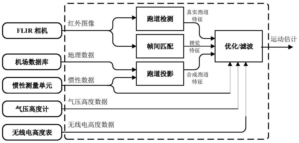
[0052] The present invention provides a visual - inertial combined navigation method for precision approach landing of aircraft, the method is to divide the entire approach landing process into three stages: the initial approach stage, the precision approach phase and the precision landing phase, for different stages of navigation by different methods. as Figure 2 As shown, the initial approach phase refers to the stage in which the aircraft descends from a flight altitude of 500 feet to 200 feet, the precision approach phase refers to the stage in which the aircraft descends from a flight altitude of 200 feet to 60 feet, and the precision landing phase refers to the stage in which the aircraft descends from a flight altitude of 60 feet to the runway surface.

[0053] The input data of this method comes from the infrared image taken by the airborne for...


PUM


Abstract

The present invention provides a visual-inertial integrated navigation method for aircraft precision approach and landing, by dividing the entire approach and landing process into three stages, namely the initial approach stage, the precision approach stage and the precision landing stage, for According to the navigation accuracy requirements of the aircraft at different stages and the characteristics of the airborne measurement information, the corresponding constraint functions are designed, the optimal solution is obtained through nonlinear optimization technology, and the motion state of the aircraft is estimated for navigation. This method can realize aircraft precision approach and landing navigation under low-visibility weather conditions without relying on the assistance of the Global Navigation Satellite System (GNSS), and has high-precision, strong real-time, and autonomous navigation capabilities.

Description

Technical field [0001] The present invention belongs to the field of computer vision navigation, specifically relates to a visual - inertial combined navigation method for precision approach landing of aircraft. Background [0002] Fixed-wing aircraft descend from the initial approach until they land on the airfield runway surface is called an approach landing. Throughout the process, the requirements for navigation accuracy of aircraft are not the same. As the aircraft's flight altitude continues to decline, the distance between the aircraft and the airport ground facilities or obstacles is getting closer and closer, the less time it can avoid ground obstacles, and the higher its requirements for its own positioning accuracy. Traditional approach landing methods include instrument landing system-guided precision approach landing and differential GPS-based precision approach landing. Among them, the guidance accuracy of the instrument landing system is low, and the ground facilit...

Claims


Application Information

Patent Timeline
Patent Type & Authority Patents(China)
IPC IPC(8): G01C21/16G01C21/20
CPCG01C21/165G01C21/20
Inventor 张磊李夏刘硕文鹏程
Owner XIAN AVIATION COMPUTING TECH RES INST OF AVIATION IND CORP OF CHINA
Learn More