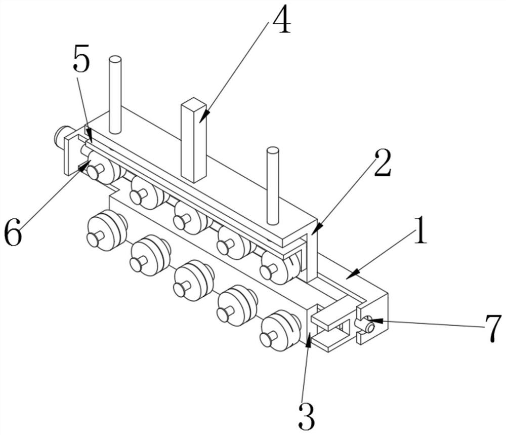
Machine head clamp for automatic threading machine for producing network transformer magnet iron core coil
A technology of network transformers and magnetic cores, which is applied in inductance/transformer/magnet manufacturing, coil manufacturing, electrical components, etc., can solve the problems of irregular magnetic core coils, affecting the normal operation of magnetic core coils, and inability to guide copper wires.
- Summary
- Abstract
- Description
- Claims
- Application Information
AI Technical Summary
Problems solved by technology
Method used
Image

Examples
Embodiment approach
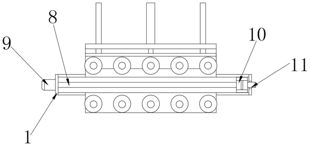
[0036] As an embodiment of the present invention, the bolt column 19 is threadedly connected with the movable wheel 18, and a handle 20 is installed at the other end of the bolt column 19. When working, the bolt column 19 is driven to rotate by turning the handle 20, and then the threaded connection is driven. The wheel 18 moves along the guide rod 21 through the guide hole 22 .
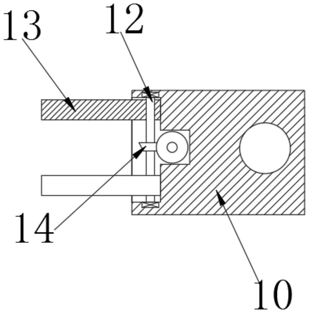
[0037] Working principle: place one end of the copper wire between the two movable clamping blocks 13, drive the second conical tooth 15 to rotate through the work of the second servo motor 11, drive the first conical tooth 14 and the second threaded rod through the meshing of the gears 12 rotates, and now the two movable clamping blocks 13 move in the second chute of the slide seat 10 until the copper wire is clamped and fixed, and the bolt column 19 is driven to rotate by turning the handle 20, and then the movable wheel 18 that is threaded is driven to pass through the guide The hole 22 moves alon...
PUM
 Abstract
Description
Claims
Application Information
 - R&D
- Intellectual Property
- Life Sciences
- Materials
- Tech Scout
- Unparalleled Data Quality
- Higher Quality Content
- 60% Fewer Hallucinations
Browse by: Latest US Patents, China's latest patents, Technical Efficacy Thesaurus, Application Domain, Technology Topic, Popular Technical Reports.
© 2025 PatSnap. All rights reserved.Legal|Privacy policy|Modern Slavery Act Transparency Statement|Sitemap|About US| Contact US: help@patsnap.com