A high-efficiency cooling and heat-dissipating device for a clad power cabinet

A technology for heat dissipation device and power cabinet, which is applied to the substation/distribution device casing, the cooling/ventilation of the substation/switchgear, and the details of the substation/switch layout, etc. and other problems, to achieve the effect of improving heat dissipation efficiency and improving the speed of heat conduction

Active Publication Date: 2021-11-26
BAIYIN POWER SUPPLY COMPANY STATE GRID GANSU ELECTRIC POWER
View PDF11 Cites 0 Cited by
  • Summary
  • Abstract
  • Description
  • Claims
  • Application Information

AI Technical Summary

Problems solved by technology

[0002] With the development of the times, people's living standards continue to improve, and power resources have become an indispensable energy source in people's lives. Transformer boxes, power distribution cabinets and other cabinets for the installation of various electrical components have also been obtained. Sufficient development, the electrical components inside the power cabinet will generate a lot of heat when they work for a long time, especially in summer, due to the small space inside the power cabinet, it is not only not conducive to the construction personnel to repair and deal with the inside of the transformer box , It also makes it difficult for the heat inside the transformer box to dissipate into the air, and it is easy to cause damage to the electrical components inside the transformer box due to high temperature or short circuit of the circuit connection wires due to high temperature, which greatly increases the hazards of using conventional power cabinets , most of the existing power cabinets are equipped with multiple sets of heat dissipation windows in terms of heat dissipation, and the heat dissipation effect is poor, especially in seasons and regions with high temperatures, the service life of such conventional power cabinets will be greatly reduced
[0003] Chinese patent (notification number CN207382773U) discloses a power cabinet cooling device for electric power. Although it can also dissipate heat through air-cooled liquid cooling, there are defects in the structural design of heat dissipation. The use environment of power components is not stable enough, and the heat dissipation efficiency is not enough. High efficiency, poor cooling effect, and single cooling mode

Method used


Image

  • A high-efficiency cooling and heat-dissipating device for a clad power cabinet
  • A high-efficiency cooling and heat-dissipating device for a clad power cabinet
  • A high-efficiency cooling and heat-dissipating device for a clad power cabinet

Examples


Embodiment 1

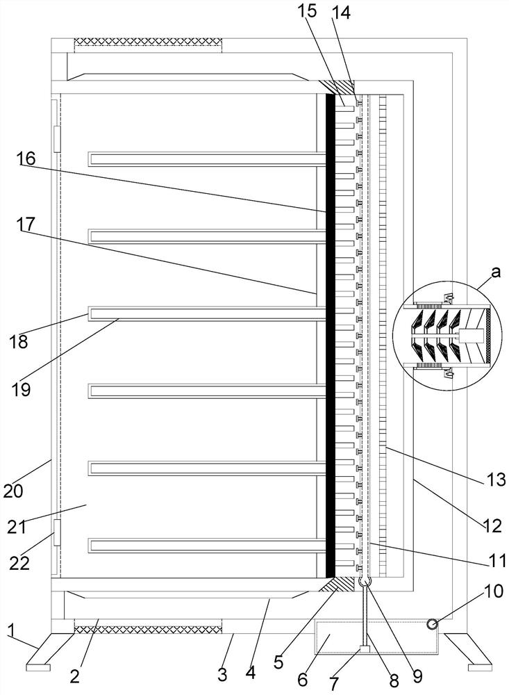
[0021] see Figure 1~3 , in an embodiment of the present invention, an efficient cooling and cooling device for a covered power cabinet includes a vertically arranged support installation cylinder 3, and support installation columns 1 are provided at the four corners of the lower end of the support installation cylinder 3, and the inside of the support installation cylinder 3 The middle position is provided with a fixed installation cylinder 21, the left side of the fixed installation cylinder 21 is connected with the support installation cylinder 3, and the left end of the fixed installation cylinder 21 is equipped with a rotary gate 20 through a hinge 22 arranged symmetrically up and down, and the inside of the fixed installation cylinder 21 The right side is vertically provided with a heat insulating plate 17, the right side of the heat insulating plate 17 is provided with a heat conducting plate 16, and the left side of the heat insulating plate 17 is equidistantly provided...

Embodiment 2

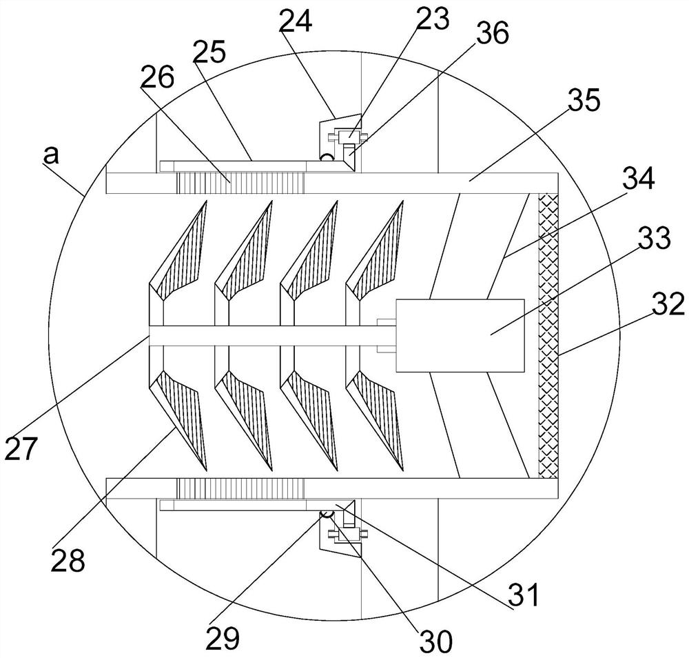
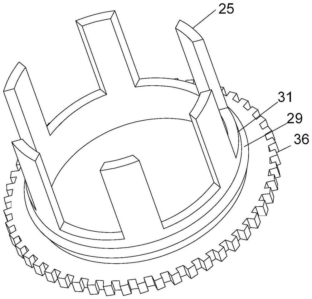
[0024] On the basis of Embodiment 1, when the driving gear 23 meshes with the rotating gear ring 36, the rotating mounting ring 31 rotates. At this time, the misalignment guide hole 26 and the misalignment guide plate 25 are misaligned or closed, thereby controlling the internal air. The efficiency of air diversion allows the air to be directly blown through the heat conduction fins, enabling the device to perform heat dissipation under low load conditions and adapt to different heat dissipation requirements.


PUM


Abstract

The present invention relates to the field of electric equipment, in particular to a high-efficiency cooling and heat dissipation device for a covered power cabinet, which includes a vertically arranged support installation cylinder, support installation columns are arranged at the four corners of the lower end of the support installation cylinder, and the inner middle position of the support installation cylinder There is a fixed installation cylinder, the left side of the fixed installation cylinder is connected with the support installation cylinder, the left end of the fixed installation cylinder is equipped with a rotating gate through a hinge arranged symmetrically up and down, and the inner right side of the fixed installation cylinder is vertically provided with a heat insulation board , the right side of the heat shield is provided with a heat conduction plate, and the right side of the fixed installation cylinder is vertically provided with a guide installation cover. By closing the installation structure of the power cabinet, the device can maintain a stable and efficient operating state for a long time. Through the heat pipe principle Efficient heat dissipation is carried out to increase the speed of heat conduction. With uniform heat dissipation and uniform atomization heat conduction, the heat dissipation efficiency of the device is significantly improved. With the dislocation conduction structure, the device also has the ability to operate with low power consumption.

Description

technical field [0001] The invention relates to the field of power equipment, in particular to a high-efficiency cooling and heat dissipation device for a covered power cabinet. Background technique [0002] With the development of the times, people's living standards continue to improve, and power resources have become an indispensable energy source in people's lives. Transformer boxes, power distribution cabinets and other cabinets for the installation of various electrical components have also been obtained. Sufficient development, the electrical components inside the power cabinet will generate a lot of heat when they work for a long time, especially in summer, due to the small space inside the power cabinet, it is not only not conducive to the construction personnel to repair and deal with the inside of the transformer box , It also makes it difficult for the heat inside the transformer box to dissipate into the air, and it is easy to cause damage to the electrical comp...

Claims


Application Information

Patent Timeline
Patent Type & Authority Patents(China)
IPC IPC(8): H02B1/56H02B1/30
CPCH02B1/30H02B1/565
Inventor 罗志诚
Owner BAIYIN POWER SUPPLY COMPANY STATE GRID GANSU ELECTRIC POWER
Why Eureka
Try Eureka