A motor with active cooling function

An active heat dissipation and functional technology, applied in electromechanical devices, electrical components, electric components, etc., can solve problems such as uneven heat dissipation, heat dissipation, and difficult motors, and achieve the effects of improving heat dissipation efficiency, avoiding vibration, and facilitating disassembly

Active Publication Date: 2021-01-29
JIAMUSI ELECTRIC MACHINE
View PDF4 Cites 0 Cited by
  • Summary
  • Abstract
  • Description
  • Claims
  • Application Information

AI Technical Summary

Problems solved by technology

[0006] The purpose of the present invention is: in order to solve the problem that the heat dissipation structure of the traditional motor is difficult to dissipate heat everywhere in the motor and prone to uneven heat dissipation, a motor with active heat dissipation function is proposed.

Method used


Image

  • A motor with active cooling function
  • A motor with active cooling function
  • A motor with active cooling function

Examples


Embodiment 1

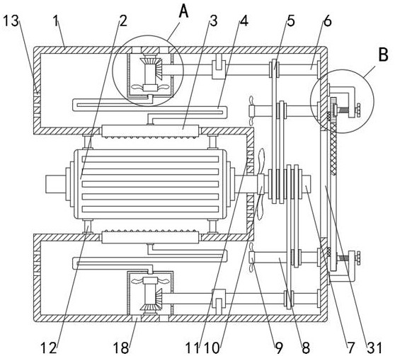
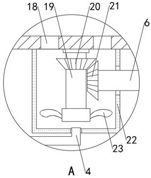
[0036] see Figure 1-5 , a motor with an active heat dissipation function, including a motor body 2 and a motor shaft 7, and a U-shaped frame 1, the motor body 2 and the side wall of the frame 1 are fixedly connected through a bracket 12, and the motor shaft 7 penetrates into the frame. The inner cavity of the frame 1 is installed with a fan blade 2 10, and the inner cavity side wall of the frame 1 is equipped with a transmission shaft 1 6 and a transmission shaft 2 8, and the transmission shaft 1 6 and the transmission shaft 2 8 and the motor shaft 7 pass through the belt 5. Transmission connection, transmission shaft 1 6 and transmission shaft 2 8 are connected with the inner wall of the frame 1 through bearings. A protective cover 22 is fixed on the inner wall, and the inner cavity of the protective cover 22 is provided with a transmission shaft three 19 and a bevel tooth one 20 and a fan blade three 23 sleeved on the transmission shaft three 19. The cavity is sleeved with...

Embodiment 2

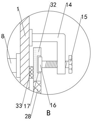
[0039] see figure 1 and figure 2 , the limiting part includes a turret 14 that rotates on the side wall of the frame 1, the turret 14 is connected with the frame 1 through a bearing, and the bending end of the turret 14 is screwed with a locking bolt 15 and the end of the locking bolt 15 The pressure block 16 is fixed, the side wall of the frame 1 is provided with a limit groove 17 which is adapted to the pressure block 16, the mounting plate 32 is adjacent to the side wall of the frame 1 and a rubber ring 33 is bonded, and the locking bolt 15 is rotated. The locking bolt 15 can drive the pressing block 16 to engage with the limiting groove 17, thereby realizing the fixing of the mounting plate 32 and the filter screen 28. This fixing method can facilitate the disassembly of the mounting plate 32 and facilitate the work. When personnel clean the filter screen 28, the rubber ring 33 is in contact with the side wall of the frame 1, which has a sealing effect.

[0040] The dif...

Embodiment 3

[0042] see figure 1 , Figure 4 and Figure 5, the buffer part includes a base 30 at the bottom of the frame 1, a damping rod 29 and an elastic part are arranged between the base 30 and the frame 1, a rubber pad 34 is bonded to the lower wall of the base 30, and the elastic part includes a fixed fixed at the bottom of the frame 1 The shell 24, the bottom of the fixed shell 24 is penetrated with a support foot 27, the bottom end of the support foot 27 is fixedly connected with the base 30, the inner cavity of the fixed shell 24 is provided with a spring 25, the top of the support foot 27 is formed with a flange 26, the flange 26 can prevent the feet 27 from disengaging from the interior of the fixed housing 24, the spring 25 can give the frame 1 and the motor body 2 a vertical buffer force, the damping rod 29 is a hydraulic damping part, and the damping rod 29 can avoid the expansion and contraction of the spring 25. The rebound makes the frame 1 vibrate violently, which impr...


PUM


Abstract

The invention discloses a motor with an active heat dissipation function, which includes a motor body, a motor shaft, and a U-shaped frame. In the present invention, the motor shaft penetrates into the inner cavity of the frame to install fan blade 2. Under the action of through hole 1, heat dissipation can be performed on the end of the motor, and the motor shaft, transmission shaft 1 and transmission shaft 2 are all driven by belt Connected, under the action of bevel gear 1 and bevel gear 2, the transmission shaft 3 drives the fan blade 3 to rotate, and under the action of the protective cover, copper pipe and wind cover, the heat dissipation can be carried out on both sides of the motor body, and the wind cover is in the shape of The arc shape is set, and heat dissipation can be carried out at multiple angles. Compared with the traditional heat dissipation device, it can effectively avoid the situation of more local heat and improve the heat dissipation efficiency. The copper tube and the airflow inside the copper tube cool down, making the heat dissipation efficiency better.

Description

technical field [0001] The present invention relates to the technical field of motors, in particular to a motor with an active heat dissipation function. Background technique [0002] Motor refers to an electromagnetic device that realizes the conversion or transmission of electrical energy according to the law of electromagnetic induction. The motor is represented by the letter M in the circuit. Its main function is to generate driving torque as a power source for electrical appliances or various machinery. [0003] In the motor, there is a resistance wound, and the power will cause loss. The loss is proportional to the square of the resistance and the current. If the current is not a standard DC or sine wave, it will also produce harmonic losses. The iron core has a hysteresis eddy current effect, which is called Copper loss also occurs in alternating magnetic fields, and its magnitude is related to material, current, frequency, and voltage, that is, iron loss. Both coppe...

Claims


Application Information

Patent Timeline
Patent Type & Authority Patents(China)
IPC IPC(8): H02K9/06H02K9/26H02K5/24H02K5/04
CPCH02K5/04H02K5/24H02K9/06H02K9/26
Inventor 朱雪峰
Owner JIAMUSI ELECTRIC MACHINE
Why Eureka
Try Eureka