Medical puncture needle

A puncture needle and medical technology, applied in the medical field, can solve the problems of easy puncture of other tissues and organs, easy to pierce blood vessels, easy occurrence of danger, etc., and achieve the effects of reducing puncture errors, delaying the puncture process, and facilitating puncture positioning.

Active Publication Date: 2020-09-15
庞爱军
View PDF11 Cites 3 Cited by
  • Summary
  • Abstract
  • Description
  • Claims
  • Application Information

AI Technical Summary

Problems solved by technology

[0002] Clinically, puncture needles are often used in infusion, blood drawing, and drainage. Usually, after the puncture needle is inserted, the sharp part of the needle can easily puncture other tissues and organs, resulting in medical accidents. Small medical accidents can be resolved by re-puncture. solution, larger medical accidents are prone to danger
[0003] In the existing patent literature, there is a scheme of setting a sleeve on the sharp part of the needle, and covering the needle with the sleeve after the puncture, so as to avoid being stabbed by the sharp part. However, most of these schemes h

Method used


Image

  • Medical puncture needle
  • Medical puncture needle
  • Medical puncture needle

Examples


Embodiment 1

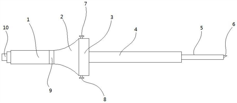
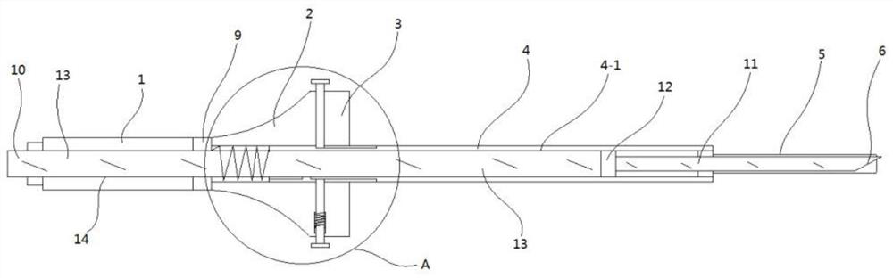
[0031] Such as figure 1 , figure 2 As shown, a medical puncture needle includes a handle 1, a fixed block 9, a connecting portion 2, a limiting portion 3, a first sleeve 4, a second sleeve 5, and a needle head 11. The front end of the needle head 11 is provided with There is a spiked part 6, and the rear end is connected with a hard guide tube 13. The second sleeve 5 is sleeved on the front part of the needle 11 and is slidably connected with the outer wall surface of the needle. The first sleeve 5 4 is fixedly connected to the rear end of the second sleeve 5, the rear end of the needle extends into the first sleeve 4, the inner wall surface of the first sleeve 4 is connected to the hard guide tube 13 The surface of the outer wall is slidingly connected, the front end of the handle 1 is fixedly connected to the rear end of the fixed block 9, or integrally formed, and the front end of the fixed block 9 is fixedly connected to the rear end of the connecting part 2, or integral...

Embodiment 2

[0035] On the basis of Embodiment 1, this embodiment has made further improvements, specifically:

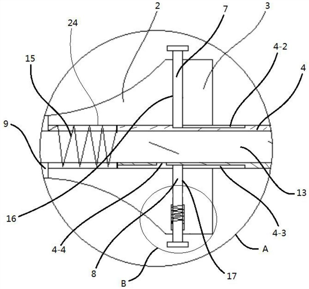
[0036] Such as image 3 As shown, the limiting part includes a first chute 4-2 located on the outer wall surface of the first sleeve 4 and arranged along the axial direction of the first sleeve 4, the rear of the first chute 4-2 The end extends into the sliding hole 24, and the first positioning hole 16 is provided on the position-limiting part 3 along the direction perpendicular to the first sleeve 4, and the first positioning rod 7 is arranged in the first positioning hole. The lower end of the first positioning rod 7 is inserted into the first chute 4-2, and is slidably connected with the first chute 4-2.

Embodiment 3

[0038] On the basis of Embodiment 2, this embodiment has made further improvements, specifically:

[0039] The front end of the second sleeve 5 completely covers the spiked portion 6. When not piercing, the lower end of the first positioning rod 7 is located in the middle of the first chute 4-2, and can be positioned along the side of the first chute 4-2. The bottom of the groove slides back and forth (not drawn among the figure, the positional relationship between the bottom of the second positioning rod 8 and the second chute 4-3 in shape, only there is no limit hole in the first chute 4-2).

[0040] In this embodiment, when puncturing, hold the handle 1, first put the two side edges of the second cannula 5 against the two sides of the blood vessel, and position the spiked part 6 contained in the second cannula to align with the midline of the blood vessel , and then gently push the handle 1 to perform the puncture action, the skin squeezes the second cannula 5, exposing the...


PUM


Abstract

The invention discloses a medical puncture needle, and relates to the technical field of medical treatment. The medical puncture needle comprises a handle, a fixing block, a connecting part, a limiting part, a first sleeve, a second sleeve and a syringe needle. The rear end is connected with a hard flow guide pipe; the second sleeve sleeves the front part of the syringe needle; the rear end of thesyringe needle extends into the first sleeve; a sliding hole is formed in the center of the connecting part and the limiting part; the first sleeve is slidably connected with the sliding hole; the rear end of the hard flow guide pipe penetrates through the rear end of the first sleeve and penetrates through the fixing block and the rear end surface of the handle; the hard flow guide pipe is fixedly connected with the fixing block and the handle; a compression spring is arranged between the fixing block and the first sleeve; and a limiting component is further arranged on the limiting part. The medical puncture needle is simple in structure and convenient to use, and the sharp spine part can be easily shielded by the second sleeve while puncture is conducted; and meanwhile, by arranging the movable second sleeve, puncture positioning can be facilitated, the puncture process is delayed, the controllable feeling of an operator is improved, and puncture errors are greatly reduced.

Description

technical field [0001] The invention relates to the field of medical technology, in particular to a medical puncture needle. Background technique [0002] Clinically, puncture needles are often used in infusion, blood drawing, and drainage. Usually, after the puncture needle is inserted, the sharp part of the needle can easily puncture other tissues and organs, resulting in medical accidents. Small medical accidents can be resolved by re-puncture. However, larger medical accidents are prone to danger. [0003] In the existing patent literature, there is a scheme of setting a sleeve on the sharp part of the needle, and covering the needle with the sleeve after the puncture, so as to avoid being stabbed by the sharp part. However, most of these schemes have complex structures and are not practical. Not widely used. [0004] In addition, during the puncturing process, because the sharp part of the needle is very sharp, it is easy to pierce the blood vessel or get out of the p...

Claims


Application Information

Patent Timeline
IPC IPC(8): A61B17/34
CPCA61B17/34A61B17/3403A61B17/3415A61B17/3417A61B17/3421A61B17/3496A61B2017/3405A61B2017/3454
Inventor 不公告发明人
Owner 庞爱军
Why Eureka
Try Eureka