[0023] The specific embodiments of the present invention will be further described below in conjunction with the drawings and embodiments. The following embodiments are only used to illustrate the technical solutions of the present invention more clearly, and cannot be used to limit the protection scope of the present invention.
[0024] The technical scheme of the present invention is:
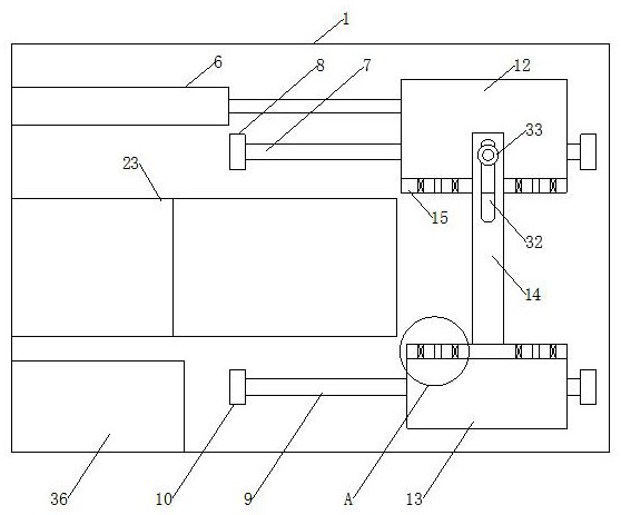
[0025] Such as Figure 1 to Figure 6 As shown, a high-efficiency heat-shrink processing equipment includes a working platform 1 provided with a heating device, a positioning device on one side of the heating device, and a driving device for driving the positioning device to move in and out of the heating device;
[0026] The heating device includes a hot air generator 2 and a first air guide assembly. The first air guide assembly includes a first bracket 3 and two first air guides 4, and the two first air guides 4 pass through the A bracket 3 is arranged on the top of the working platform 1, the first air guiding hood 4 is provided with a first air guiding cavity, and the top of the first air guiding hood 4 is provided with a hot air outlet communicating with the first air guiding cavity The hot air generator 2 is arranged at the bottom of the working platform 1, and the air outlet of the hot air generator 2 is connected with two hot air pipes 5 corresponding to the two first air guide hoods 4 one by one. The other end of 5 penetrates the working platform 1 and the first bracket 3 and extends into the first air guide cavity corresponding to the first air guide 4;
[0027] The driving device includes a driving cylinder 6, a first guide assembly and a second guide assembly. The first guide assembly and the second guide assembly are respectively located on both sides of the first bracket 3. The first guide assembly includes a first X A shaft guide rod 7, both ends of the first X-axis guide rod 7 are respectively provided with a first support seat 8 fixed to the work platform 1, and the first X-axis guide rod 7 is provided with a first slide plate in a sliding sleeve, so The output shaft of the driving cylinder 6 is fixedly connected to the first sliding plate, and the second guide assembly includes a second X-axis guide rod 9, and two ends of the second X-axis guide rod 9 are respectively provided with a first fixed to the working platform 1. Two supporting seats 10, and the second X-axis guide rod 9 is slidingly sleeved with a second slide plate 11;
[0028] The positioning device includes a first positioning plate 12 arranged on the top of the first sliding plate, a second positioning plate 13 arranged on the top of the second sliding plate 11, and an adjustment connected between the first positioning plate 12 and the second positioning plate 13. The side of the first positioning plate 12 facing the second positioning plate 13 extends upward to form a first positioning protruding strip 15. The first positioning protruding strip 15 is provided with two first positioning grooves. The side portion of the positioning plate 13 facing the first positioning plate 12 extends upward to form a second positioning protruding strip 16, and the second positioning protruding strip 16 is provided with two second positioning grooves 17 corresponding to the two first positioning grooves. , The first positioning groove and the second positioning groove 17 are both provided with a clamping assembly, the clamping assembly includes two movable clamping blocks 18, the two movable clamping blocks 18 opposite sides are clamping surfaces 19, and The opposite sides of the two movable clamping blocks 18 are respectively connected with clamping springs 20, the top of the clamping surface 19 is provided with a guiding inclined surface 21, and the junction of the clamping surface 19 and the guiding inclined surface 21 is provided with an arc transition 面22.
[0029] The above heating device further includes a mounting frame 23 and a second air guide assembly. The mounting frame 23 is arranged on the top of the working platform 1, the mounting frame 23 is of an L-shaped structure, and an L-shaped cavity is provided inside the mounting frame 23 , The mounting frame 23 includes a vertical portion 24 and a horizontal portion 25 connected to the top end of the vertical portion 24, the second air guide assembly includes a second bracket 26 and two second air guides 27, the two The second wind deflector 27 is arranged on the vertical part 24 through the second bracket 26. The two second wind deflectors 27 correspond to the two first wind deflectors 4 one by one. A second air guide cavity is provided inside, and the bottom of the second air guide 27 is provided with a recovery port located directly above the corresponding first air guide 4, and the bottom of the horizontal portion 25 is provided with an L-shaped cavity, And two recovery air ducts 28 corresponding to the two second air guides 27 one-to-one, the other end of the recovery air duct 28 penetrates the second bracket 26 and extends to the second air guide of the second air guide 27 In the cavity, the air inlet of the hot air generator 2 is provided with a connecting pipe 29. The other end of the connecting pipe 29 penetrates the work platform 1 and extends into the L-shaped cavity of the mounting frame 23.
[0030] The top of the second slide plate 11 is provided with a Y-axis sliding groove 30, and the bottom of the second positioning plate 13 is provided with a sliding block 31 connected with the Y-axis sliding groove 30; one end of the adjusting plate 14 is connected to the second The positioning protrusion 16 is fixedly connected, the adjustment plate 14 is provided with a long adjustment hole 32, the length direction of the adjustment hole 32 is consistent with the length direction of the Y-axis sliding groove 30, and the adjustment hole 32 is provided with The first positioning plate 12 is screwed and used for pressing the pressing bolt 33 of the adjusting plate 14.
[0031] An air guiding plate 34 is provided in the first air guiding cavity, and a plurality of air outlet holes 35 are provided on the air guiding plate 34.
[0032] An electric control box 36 is provided on the above-mentioned working platform 1.
[0033] The bottom of the working platform 1 is provided with four supporting feet 37, and the four supporting feet 37 are arranged in a rectangular shape.
[0034] The advantages and beneficial effects of the present invention are that it provides a high-efficiency heat-shrink processing equipment with reasonable structure, high production efficiency and good heat-shrinking effect on heat-shrinkable tubes.
[0035] When in use, the positioning device can fix two heat shrinkable tubes, so that the two heat shrinkable tubes can be heat-shrinked at the same time. When fixing the heat shrinkable tube, the two ends of the heat shrinkable tube are respectively placed in the first positioning groove and the second positioning groove 17, and one end of the heat shrinkable tube is clamped by the two movable clamping blocks 18 in the first positioning groove. The two movable clamping blocks 18 in the second positioning groove 17 clamp the other end of the heat shrinkable tube; and, by providing a guiding inclined surface 21 on the clamping surface 19 of the movable clamping block 18, the heat shrinkable tube is guided to be stuck between the two Between the two movable clamp blocks 18, it is also convenient to take out the heat shrinkable tube; after the heat shrinkable tube is fixed, the output shaft of the driving cylinder 6 is started to retract, thereby driving the positioning device and the heat shrinkable tube fixed on the positioning device Move to the heating device so that the heat shrinkable tube is located between the corresponding first air guide hood 4 and the second air guide 27 in the heating device, and the hot air generated by the hot air generator 2 flows through the hot air tube 5 and the first air guide The cover 4 is blown out from the air outlet to make the heat shrinkable tube shrink under the action of hot air. After completion, the output shaft of the driving cylinder 6 is started to extend, thereby driving the positioning device and the heat shrinkable tube that has completed the heat shrinking process to move out of the heating device, and finally the operator takes out the processed heat shrinkable tube.
[0036] In addition, by providing two second wind deflectors 27 above the two first wind deflectors 4, the hot air blown out from the first wind deflectors 4 can be collected by the second wind deflectors 27, and then recovered through the wind The pipe 28, the L-shaped cavity and the connecting pipe 29 are introduced into the hot air generator 2, and the hot air generator 2 is heated again and then used again, which helps to save the energy consumption of the hot air generator 2.
[0037] In addition, since the first positioning plate 12 and the second positioning plate 13 are connected by the adjusting plate 14, the distance between the first positioning plate 12 and the second positioning plate 13 can be adjusted, that is, the first positioning groove and the second positioning plate can be adjusted. The distance between the two positioning grooves 17 is to fix heat shrinkable tubes of different lengths. During the specific operation, first loosen the pressing bolt 33. Since the second positioning plate 13 and the second sliding plate 11 are slidably connected, the second positioning plate 13 can be moved closer to or away from the first positioning plate 12. After the plate 13 is moved into position, the pressing bolt 33 is tightened to press and fix the adjusting plate 14 on the first positioning plate 12 to complete the adjustment of the distance between the first positioning plate 12 and the second positioning plate 13.
[0038] The above are only the preferred embodiments of the present invention. It should be pointed out that for those of ordinary skill in the art, without departing from the technical principles of the present invention, several improvements and modifications can be made. These improvements and modifications It should also be regarded as the protection scope of the present invention.