Overturning device and overturning method for fragile slices

A technology of turning device and sheet, applied in the field of automation, can solve the problems of easy deformation, cracking, excessive deformation of the sheet, etc., and achieve the effect of avoiding cracking

Active Publication Date: 2020-09-15
邳州市景鹏创业投资有限公司
View PDF8 Cites 4 Cited by
  • Summary
  • Abstract
  • Description
  • Claims
  • Application Information

AI Technical Summary

Problems solved by technology

[0003] When flipping a fragile sheet, because of its small thickness, it is easy to arch the sheet directly from the edge and break it. In the prior art, a rotary flipping mechanism is used to flip the sheet. The mechanism and the conveyor belts on both sides perform step-by-step rotation, and the step-by-step conveyor belts are used to send the sheets to the multiple compartments of the turning mechanism at intervals. Rotate and turn over, and send the turned sheet out from the other side of the conveyor belt to realize the turnover operation, but in the process of actual turning operation, due to the small thickness of the sheet, it is easy to deform, so that one side of the turning mechanism feeds The position where the bottom of the sheet is in contact with the conveyor belt is likely to generate adsorption force, and the other side of the sheet is prone to excessive deformation during the rotation of the turning mechanism, resulting in chip fragmentation

Method used


Image

  • Overturning device and overturning method for fragile slices
  • Overturning device and overturning method for fragile slices
  • Overturning device and overturning method for fragile slices

Examples


Embodiment 1

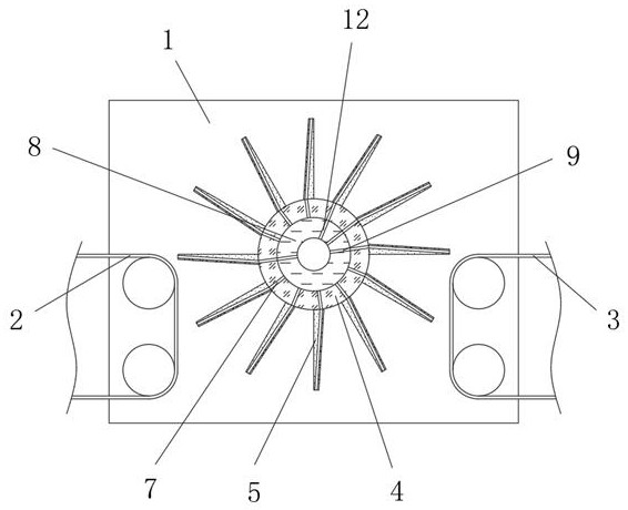
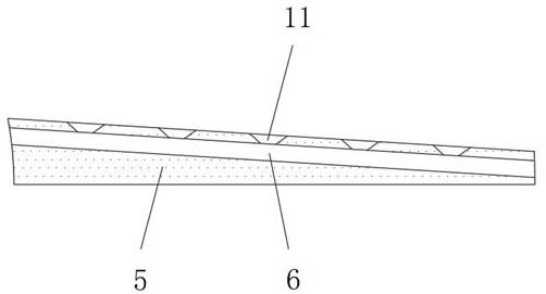
[0024] refer to Figure 1-2 , a turning device for fragile sheets, including two fixed frames 1, the two sides between the two fixed frames 1 are respectively provided with a feed conveyor belt 2 and a discharge conveyor belt 3, and the two fixed frames 1 The intermediate position between the feed conveyor belt 2 and the discharge conveyor belt 3 is rotatably connected with a rotating roller 4, and one end of the rotating roller 4 is connected with a stepping motor, and the outer wall of the rotating roller 4 is fixed with partitions distributed in a ring array. Part 5, and the partition 5 above the rotating roller 4 moves to the side close to the discharge conveyor belt 3. One end of the rotating roller 4 is provided with a flow chamber, and one end of the flow chamber is connected to a blower through an air duct. The inner wall of the flow chamber The position corresponding to the partition 5 is provided with air holes 7 equidistantly distributed in the horizontal direction,...

Embodiment 2

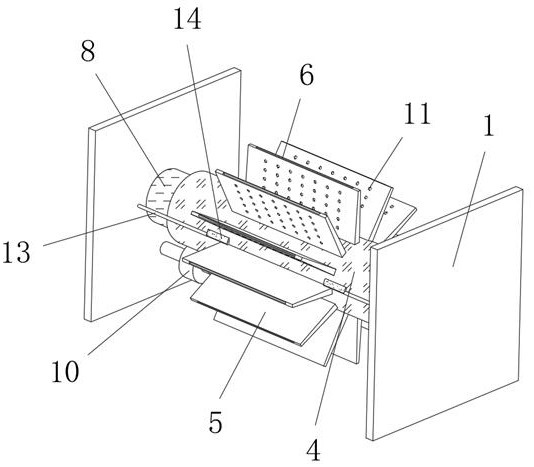
[0028] refer to Figure 1-3, a flipping device for fragile sheets, further on the basis of Embodiment 1, a fixed cylinder 8 is fixed between the two fixed frames 1 corresponding to the flow chamber, and the inner wall of the rotating roller 4 is in contact with the fixed cylinder The outer wall of 8 is slidingly connected, and one end of the fixed cylinder 8 is connected with a blower through the air duct, the stepper motor is fixed on the bottom of the fixed frame 1, the output shaft of the stepper motor is fixed with a drive ring 10, and the outer wall of the drive ring 10 is connected to the rotating roller 4 One end of the outer wall is engaged, and a plurality of through holes 9 are opened on both sides of the fixed cylinder 8 corresponding to the feeding part and the discharging part, and the through holes 9 communicate with the air holes 7. The rotation makes a plurality of air holes 7 communicate with the through holes 9 in turn, and only the air cavity 6 at the positi...

Embodiment 3

[0033] refer to Figure 1-4 , a flipping device for fragile sheets, further on the basis of Embodiment 1 or Embodiment 2, a horizontally placed fixing member 13 is fixed at the position corresponding to the outer wall of one end of the two fixing frames 1 and the feeding member, and the fixed One end of the piece 13 is fixed with a rubber strip 14, the bottom of the rubber strip 14 abuts against the top of the feed piece, and the sheet sent from the feed conveyor belt 2 to the top of the feed piece hits the rubber strip 14 to avoid direct contact with the rotating The impact of the outer wall of the roller 4 causes fragmentation. When the rotating roller 4 is stepping and rotating, the rubber strip 14 bends and moves relative to the feed piece and stays on the top of the next separator 5. The rubber strip 14 is arranged on both sides to reduce friction and Ensure the integrity of continuous operations;

[0034] The bottom of the rubber strip 14 is arranged in an arc-shaped st...


PUM


Abstract

The invention discloses an overturning device and an overturning method for fragile slices. The device comprises two fixed frames, a feeding conveying belt and a discharging conveying belt are arranged on the two sides between the two fixed frames respectively, a rotating roller is rotationally connected to the middle position between the two fixed frames, and one end of the rotating roller is intransmission connection with a stepping motor; separators distributed in an annular array mode are fixed to the rotating roller, and a distribution cavity is formed in one end of the rotating roller.The method comprises the steps of blowing air to the top surface of the feeding conveying belt by utilizing air cavities of feeding pieces at the same time, and separating the bottoms of the positions, extending into the feeding pieces, of the sheets from the top surface wall of the feeding conveying belt. The air cavities are used for blowing air to the top surface of the feeding conveying belt,so that the bottoms of the positions, extending into the feeding pieces, of the sheets can be separated from the top surface wall of the feeding conveying belt, and the situation that the bottom of each slice is excessively deformed and broken due to adsorption to the top of the feeding conveying belt can be avoided.

Description

technical field [0001] The invention relates to the field of automation technology, in particular to an overturning device and an overturning method for fragile sheets. Background technique [0002] Automation refers to the process of automatic detection, information processing, analysis and judgment, manipulation and control of machines, equipment, systems or processes (production, management processes) without the direct participation of people or fewer people, according to people's requirements, to achieve the expected goals. process, in the process of automatic processing of sheet materials, the assembly line is generally formed by driving the roller to rotate the conveyor belt to carry out step-by-step conveyance of the sheet to the corresponding station. Flip over to process both sides of the sheet separately. [0003] When flipping a fragile sheet, because of its small thickness, it is easy to arch the sheet directly from the edge and break it. In the prior art, the ...

Claims


Application Information

Patent Timeline
Patent Type & Authority Applications(China)
IPC IPC(8): B65G47/248B65G47/84B65G49/06
CPCB65G47/248B65G47/84B65G49/06
Inventor 侯玉梅
Owner 邳州市景鹏创业投资有限公司
Why Eureka
Try Eureka