
Eureka
For R&D, Eureka makes reading and utilizing patents & technical documents easy.
Eureka AIR
Designed for self-driven R&D workflows. Generate viable solutions, solve complex R&D challenges, empower your innovation with AI.

Eureka Materials
Designed for material experts only. Revolutionize your material R&D, from search, analyze, to developing new materials.

TechResearch
Generate reliable direction feasibility study reports for your R&D in just a few steps.

TechSeek
Discover and master advanced knowledge NOW. Basics, ideas, possibilities, all at once.

TechMind
As an expert in R&D Theories, TechMind can generates customized viable solutions instantly.

TechRisk
Analyze your overall solution with one click, know your potential R&D risks in advance.

TechMonitor
Get weekly tech updates, stay abreast of the latest tech innovations and key insights.
Non-contact delivering device for medical instrument
A medical device, contact-free technology, applied in the medical field, can solve the problems of low degree of automation in the delivery process and high risk of virus transmission by manual transmission, and achieve the effects of avoiding the possibility of contamination, high degree of automation, and convenient operation.
- Summary
- Abstract
- Description
- Claims
- Application Information
AI Technical Summary
Problems solved by technology
Method used
Image

Examples
Embodiment 1
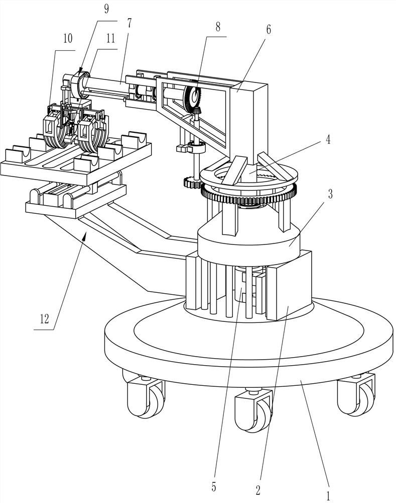
[0028] A contact-free delivery device for medical devices, such as Figure 1-3 As shown, it includes a vehicle frame 1, a support plate 2, a fixed seat 3, a first rotating rod 4, a servo motor 5, a rotating frame 6, a second rotating rod 7, a transmission mechanism 8, a rotating device 9 and a clamping device 10, The specific installation relationship is:
[0029] The left and right sides of the vehicle frame 1 are connected with support plates 2, the upper sides of the support plates 2 are connected with a fixed base 3, the fixed base 3 is rotatably connected with a first rotating rod 4, and the support plates 2 are connected with a servo motor 5. The output shaft of the servo motor 5 is connected to the lower side of the first rotating rod 4. The upper side of the first rotating rod 4 is connected to the rotating frame 6. The right side of the rotating frame 6 is connected to the second rotating rod 7 in a rotating manner. The left side of the rod 7 is provided with a trans...
Embodiment 2
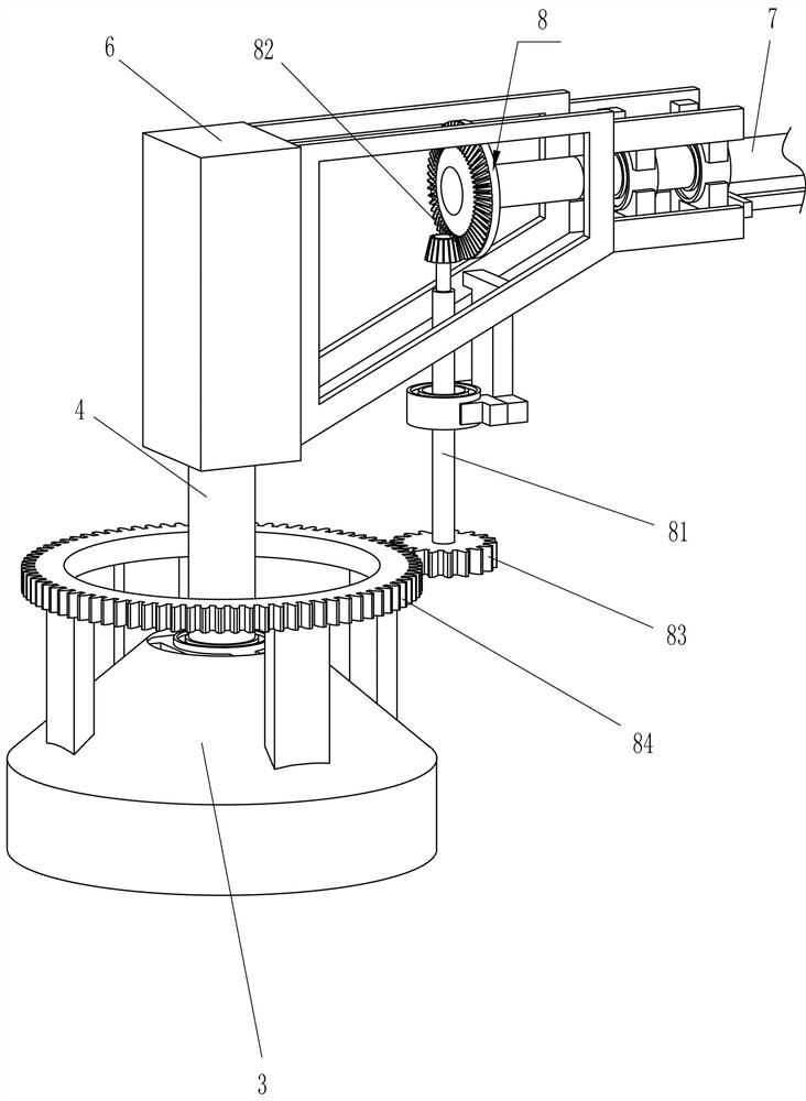
[0032] On the basis of Example 1, such as Figure 4-7 As shown, the transmission mechanism 8 includes a first rotating shaft 81, a gear transmission assembly 82, a first round gear 83 and a gear ring 84, and the specific installation relationship is as follows:
[0033] A first rotating shaft 81 is rotatably connected between the lower right side of the rotating frame 6, a gear transmission assembly 82 is connected between the first rotating shaft 81 and the left side of the second rotating rod 7, and a first round gear is connected to the lower side of the first rotating shaft 81. 83, the upper side of the fixed base 3 is connected with a gear ring 84, and the gear ring 84 meshes with the first round gear 83.
[0034]When the first rotating rod 4 drives the rotating frame 6 to rotate counterclockwise, the rotating frame 6 will drive the first rotating shaft 81 to rotate counterclockwise around the first rotating rod 4, thereby driving the first circular gear 83 to rotate coun...
Embodiment 3
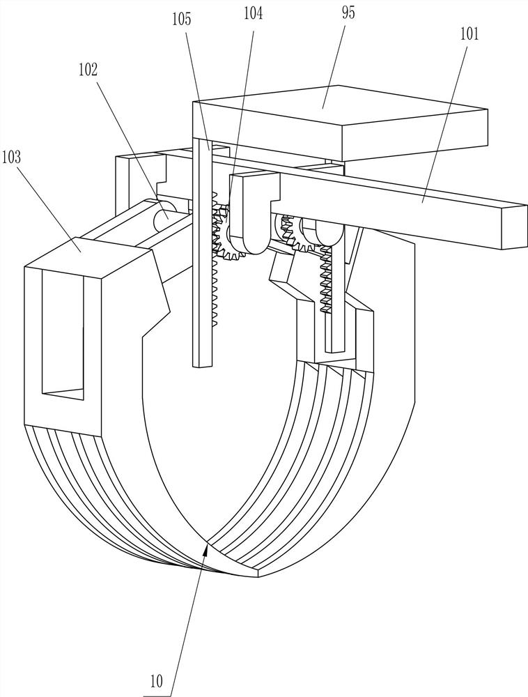
[0042] On the basis of Example 2, such as Figure 8-9 As shown, a positioning device 11 is also included. The positioning device 11 includes a second guide rail 110, a second guide sleeve 111, a third guide sleeve 112, an elastic member 113 and a positioning block 114. The specific installation relationship is:
[0043] The positioning device 11 is arranged under the mounting rod 101. The positioning device 11 is used to stabilize the clamped medical device. The middle part of the lower side of the mounting rod 101 is connected with a second guide rail 110, and the second guide rail 110 is slidably connected with a second guide sleeve. 111 and the third guide sleeve 112, an elastic member 113 is connected between the second guide sleeve 111 and the third guide sleeve 112, the second guide sleeve 111 is connected with the rack 105, and the lower side of the third guide sleeve 112 is connected with a positioning block 114 .
[0044] When the rack 105 moves away from the second ...
PUM
 Abstract
Description
Claims
Application Information
 - R&D Engineer
- R&D Manager
- IP Professional
- Industry Leading Data Capabilities
- Powerful AI technology
- Patent DNA Extraction
Browse by: Latest US Patents, China's latest patents, Technical Efficacy Thesaurus, Application Domain, Technology Topic, Popular Technical Reports.
© 2024 PatSnap. All rights reserved.Legal|Privacy policy|Modern Slavery Act Transparency Statement|Sitemap|About US| Contact US: help@patsnap.com