Dsetection equipment capable of displaying state of mechanical limit switch

A technology of limit switch and detection equipment, which is applied in the testing of mechanical parts, testing of machine/structural parts, measuring devices, etc. It can solve problems such as troubleshooting difficulties, personal casualties, on-site accidents, etc., and achieve fast and effective troubleshooting of limit faults , The application is fast and effective, and the effect of improving efficiency

Pending Publication Date: 2020-09-15
大连宝信起重技术有限公司
View PDF0 Cites 0 Cited by
  • Summary
  • Abstract
  • Description
  • Claims
  • Application Information

AI Technical Summary

Problems solved by technology

However, the mechanical limit still needs to be checked regularly, otherwise it may cause on-site accidents due to damage to the mechanical limit, ranging from equipment damage to personal injury or death.
[0003] However, since the mechanical limit is a fully enclosed device, it is usually done manually during maintenance and inspection.
[0004] Manually toggle the limiter to judge whether the limit is valid, but there is no display device for the mechanical limiter, usually two people are required to cooperate, one person toggles the limiter, and the other starts the device or uses a multimeter and other monitoring equipment to judge the limiter Is it efficient, very inefficient
In addition, such as the pull rope limit of the raw material conveying belt, a pull rope limit is usually set every ten meters or even tens of meters. In the conveying range of several kilometers, there are as many as hundreds of pull rope limits. This method is obviously unrealistic, especially when one or more pull ropes are damaged or mishandled, it is usually very difficult to quickly troubleshoot

Method used


Image

  • Dsetection equipment capable of displaying state of mechanical limit switch
  • Dsetection equipment capable of displaying state of mechanical limit switch
  • Dsetection equipment capable of displaying state of mechanical limit switch

Examples


Embodiment Construction

[0034] Detection equipment that can display the status of mechanical limit switches:

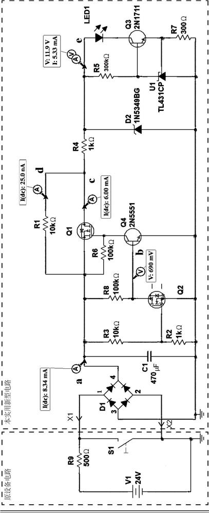
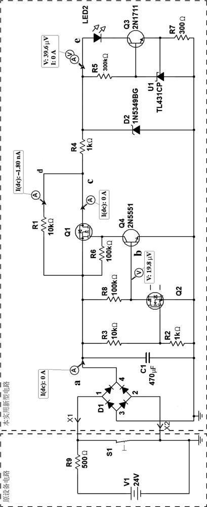
[0035] figure 1 and figure 2 It is the working principle diagram of the present invention when the field equipment adopts 24VDC power supply.

[0036] principle figure 1 The circuit in the dotted line box on the left side of the figure is the simulation of the field circuit of the original equipment. R9 is to display the load in the line (usually a relay). S1 is the control limit in the line, usually one, and there may be many in some applications (such as the pull rope limit of the raw material conveying belt), this figure 1 A limit switch is used for simulation, and V1 is the power supply of the original circuit.

[0037] Book figure 1 It is the actual running result of NI Multisim software simulation. When the limit S1 is disconnected, a voltage will be generated at both ends of S1, and since the circuit is disconnected, the power supply is the same as the power supply voltage, th...


PUM


Abstract

Detection equipment capable of displaying the state of a mechanical limit switch comprises a rectifier bridge, a filter capacitor C1, an MOSFET tube Q1, an MOSFET tube Q2, a triode Q3, a triode Q4, aprecision voltage stabilization source chip U1 and a plurality of resistors. The equipment is directly connected in parallel with two terminals of a switch to be detected through two probes or bindingposts. The current on-off state of a mechanical limit can be detected on line in real time, when the switch is in an on state, the equipment indicates that the current switch is in the on state through a highlighted LED indicating lamp, and when the switch is in an off state, the highlighted LED indicating lamp is turned off, which indicates that the switch is in an on state. Therefore, long-termlimiting state observation can be realized, the labor cost of troubleshooting personnel can be reduced, and the limiting inspection and maintenance efficiency can be improved.

Description

technical field [0001] The invention belongs to the field of detection equipment for switch states, in particular to detection equipment capable of displaying the state of a mechanical limit switch. Background technique [0002] Mechanical limit has a wide range of applications in the crane industry. At the same time, mechanical limit also plays a vital role in the crane industry. It has a wide range of aspects such as overspeed detection, overtravel detection, limit detection and area limit detection. Applications. In addition to general-purpose cranes, limit stops are widely used in many industrial fields, because mechanical stops have many advantages such as reliable operation, high temperature resistance and long service life. For example, the belt pull rope limit used in a large number of raw material belt conveying equipment in the metallurgical industry is the mechanical limit used, and so on. However, the mechanical limit still needs to be checked regularly, otherw...

Claims


Application Information

Patent Timeline
Patent Type & Authority Applications(China)
IPC IPC(8): G01M13/00
CPCG01M13/00
Inventor 尹建华
Owner 大连宝信起重技术有限公司
Why Eureka
Try Eureka