Radiation dose detection device and method for blood irradiator
A technology of radiation dose and detection device, applied in the field of radiation dose detection device, can solve the problems of film method dose range limitation, high cost, complicated operation in detection process, etc.
- Summary
- Abstract
- Description
- Claims
- Application Information
AI Technical Summary
Problems solved by technology
Method used
Image
Examples
Embodiment 1
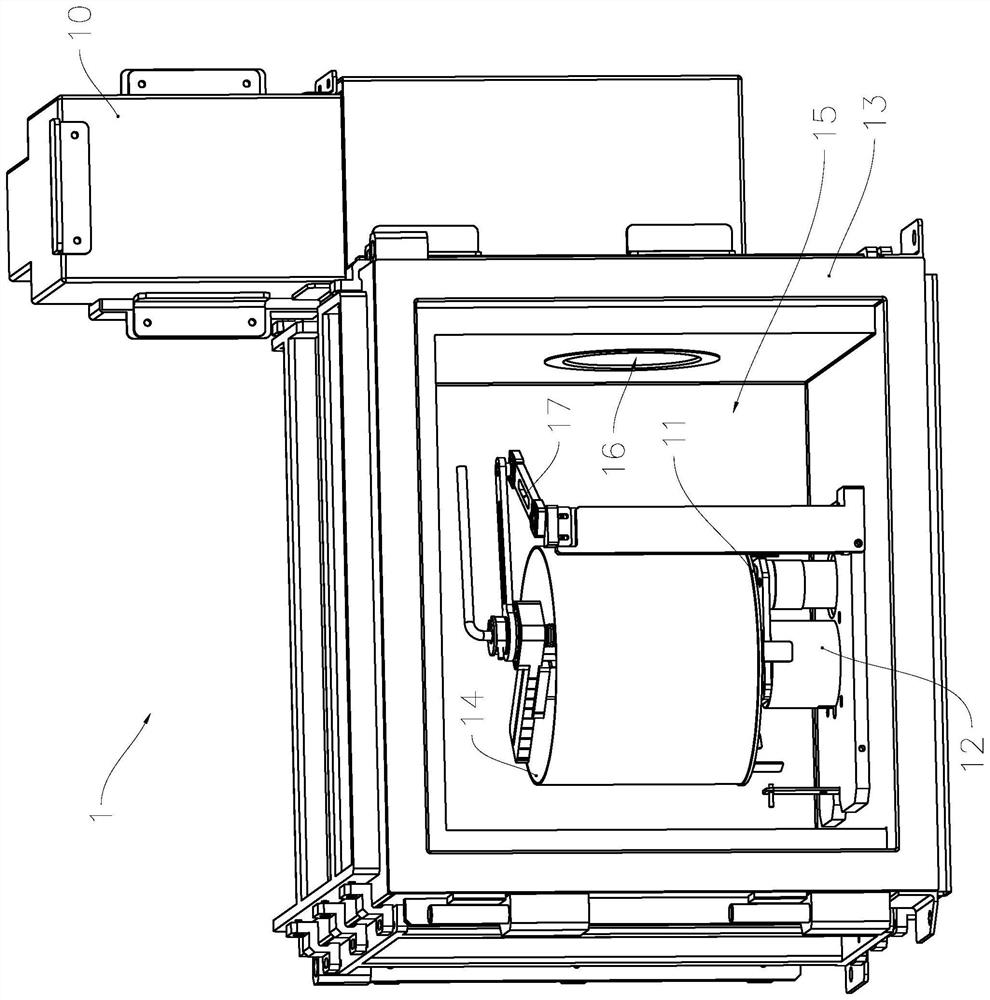
[0054] see image 3 The blood irradiation instrument 1 includes a ray generator 10, a blood cup tray 11, a blood cup tray rotation drive mechanism 12 for driving the blood cup tray 11 to rotate, a shielding shell 13, and a detection blood cup placed on the blood cup tray 11 14; Wherein, the blood cup tray 11 is rotatably installed in the irradiation chamber 15 surrounded by the shielding case 13 . A ray passing hole 16 is provided on the shielding shell 13. During the process of irradiating blood products and detecting the radiation dose, the ray generator 10 will emit high-energy rays to the irradiation chamber 15 through the ray passing hole 16. In this embodiment, it is specifically X-rays, that is, the ray generator 10 includes an X-ray tube.
[0055] Such as Figure 3 to Figure 12 Shown is the structure of the radiation dose detection device 17 of the present invention, which is used to detect the radiation dose in the area surrounded by the blood cup 14, including the ...
Embodiment 2
[0074] As a description of Embodiment 2 of the present invention, only the differences from Embodiment 1 above will be described below.
[0075] Such as Figure 13 As shown, the first link mechanism 3 is a double crank mechanism, and the hinged position of the connecting member 6, the transverse connecting rod 5 and the connecting rod 61 is set to be adjustable along the axial direction of the rod, so that the blood cup can also be detected at any time. 14 In the process of turning, realize the problem of anti-winding. That is, in this embodiment, the two rigid members on the second link mechanism are connected by a rotation pair, and the other end thereof is connected to the fixed bracket 30 by a rotation pair.
Embodiment 3
[0077] As an explanation of Embodiment 3 of the present invention, only the differences from Embodiment 1 above will be described below.
[0078] Such as Figure 14 As shown, the link rod in the above embodiment is replaced by a slider 61, and a guide rail 301 matching the slider 61 is provided on the fixed bracket, so that the first link mechanism 3 is a slider crank mechanism . That is, in this embodiment, the two rigid members on the second link mechanism are connected by a rotating pair, and the other end of the second link mechanism is connected to the fixed bracket through a moving pair.
PUM
 Abstract
Description
Claims
Application Information
 - R&D
- Intellectual Property
- Life Sciences
- Materials
- Tech Scout
- Unparalleled Data Quality
- Higher Quality Content
- 60% Fewer Hallucinations
Browse by: Latest US Patents, China's latest patents, Technical Efficacy Thesaurus, Application Domain, Technology Topic, Popular Technical Reports.
© 2025 PatSnap. All rights reserved.Legal|Privacy policy|Modern Slavery Act Transparency Statement|Sitemap|About US| Contact US: help@patsnap.com


