Optical module

An optical module and optical transceiver technology, applied in the field of optical communication, can solve the problems of faster transmission rate and high cost, achieve the effect of small lens array structure, correct position deviation, and meet the effect of miniaturized packaging

Inactive Publication Date: 2020-09-15
INNOLIGHT TECHNOLOGY (SUZHOU) LTD
View PDF6 Cites 0 Cited by
  • Summary
  • Abstract
  • Description
  • Claims
  • Application Information

AI Technical Summary

Problems solved by technology

At present, multi-mode is mostly carried out in multi-channel parallel mode, but its cost is high, and the transmission rate cannot meet the faster requirements

Method used


Image

  • Optical module
  • Optical module
  • Optical module

Examples


Embodiment Construction

[0030] The present invention will be described in detail below in conjunction with specific embodiments shown in the accompanying drawings. However, these embodiments do not limit the present invention, and any structural, method, or functional changes made by those skilled in the art according to these embodiments are included in the protection scope of the present invention.

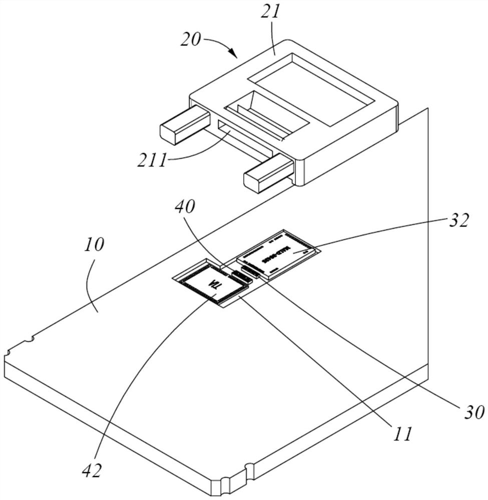
[0031] Such as Figure 1 to Figure 8 As shown, in one embodiment of the present invention, the optical module includes a housing (not shown), a substrate 10 disposed in the housing, electronic components disposed on the substrate 10, a light emitting element 30 disposed on the substrate and a light receiving The element 40 and the optical device 20 are arranged in the housing, the light emitting element 30 and the light receiving element 40 are arranged between the optical device 20 and the substrate 10 , and the optical device 20 is arranged above the light emitting element 30 and the light receiving ...


PUM


Abstract

The invention discloses an optical module. The optical module comprises a shell, a substrate arranged in the shell, an optical device arranged in the shell, and a plurality of light emitting elementsand a plurality of light receiving elements which are arranged on the substrate; the plurality of light emitting elements and the plurality of light receiving elements are arranged between the opticaldevice and the substrate; the optical device is arranged above the plurality of light emitting elements and the plurality of light receiving elements; the optical device comprises a device body, andan optical transceiving interface and a lens array which are arranged on the device body. Optical signals emitted by the plurality of optical emitting elements are transmitted to the outside of the optical module through the optical transceiving interface. Optical signals transmitted from the outside of the optical module reach the plurality of optical receiving elements through the optical transceiving interface, the lens array can enable the plurality of optical transmitting elements and the optical transceiving interface to be optically coupled and the optical transceiving interface and theplurality of optical receiving elements to be optically coupled, and an auxiliary lens is arranged on an optical coupling path. The light divergence angle is reduced, and higher coupling efficiency is obtained.

Description

technical field [0001] The invention relates to the technical field of optical communication, in particular to an optical module. Background technique [0002] In recent years, optical interconnection technology has been widely used, which is a technology for transmitting signals at high speed within system equipment and between equipment or between optical modules. That is, optical interconnection is a technology that treats optical devices as electrical components and mounts optical devices on motherboards or circuit substrates, such as those used in personal computers, vehicles, and optical transceivers. [0003] With the rapid development of technology, optical communication modules are required to have faster transmission rates and lower costs, requiring modules with the same density to have several times the communication rate and communication volume. At present, multi-mode is mostly carried out in multi-channel parallel mode, but its cost is high, and the transmissi...

Claims


Application Information

Patent Timeline
IPC IPC(8): G02B6/42
CPCG02B6/4206G02B6/4207G02B6/4214H04B10/40G02B3/005
Inventor 韩明萧越
Owner INNOLIGHT TECHNOLOGY (SUZHOU) LTD
Why Eureka
Try Eureka