
Buried wind-heat combined park self-sprinkling system for cities in plateau

A buried and integrated technology, which is applied in the direction of wind power motor combination, wind power storage power generator, application, etc., can solve the problems of affecting the city's aesthetics, consuming large labor force, and low work efficiency, so as to save labor force and improve work efficiency. Efficiency and energy saving effect

Pending Publication Date: 2020-09-18
江勇
View PDF6 Cites 0 Cited by
  • Summary
  • Abstract
  • Description
  • Claims
  • Application Information

AI Technical Summary

Problems solved by technology

[0003] However, since there are green plants planted, it is necessary to water the green plants, especially in some plateau cities, where the air is dry and the temperature is high, and the plants have a greater demand for water. If the water demand of the plants cannot be met, then The plants in the park are easy to die due to drought. On the one hand, it affects the aesthetics of the city. On the other hand, people need to replace the dead plants, causing unnecessary trouble. However, the existing watering methods generally use artificial water pumps and Tools such as water pipes are used for sprinkling water. Due to the large number of parks in the city and the large range of parks, and the plants need to be watered several times a day, manual sprinkling requires a lot of labor and low work efficiency. Working for a long time in the environment is also prone to heat stroke. Therefore, it is necessary to design a self-sprinkling system for parks with a combination of wind and heat in the plateau city to solve the above problems.

Method used


Image

  • Buried wind-heat combined park self-sprinkling system for cities in plateau
  • Buried wind-heat combined park self-sprinkling system for cities in plateau

Examples


Embodiment Construction

[0021] The technical solutions in the embodiments of the present invention will be clearly and completely described below in conjunction with the accompanying drawings in the embodiments of the present invention. Obviously, the described embodiments are only a part of the embodiments of the present invention, rather than all the embodiments.

[0022] In the description of the present invention, it should be understood that the terms "upper", "lower", "front", "rear", "left", "right", "top", "bottom", "inner", " The orientation or positional relationship indicated by “outside” is based on the orientation or positional relationship shown in the drawings, and is only for the convenience of describing the present invention and simplifying the description, and does not indicate or imply that the device or element referred to must have a specific orientation to The specific azimuth structure and operation cannot be understood as a limitation of the present invention.

[0023] Reference ...


PUM


Abstract

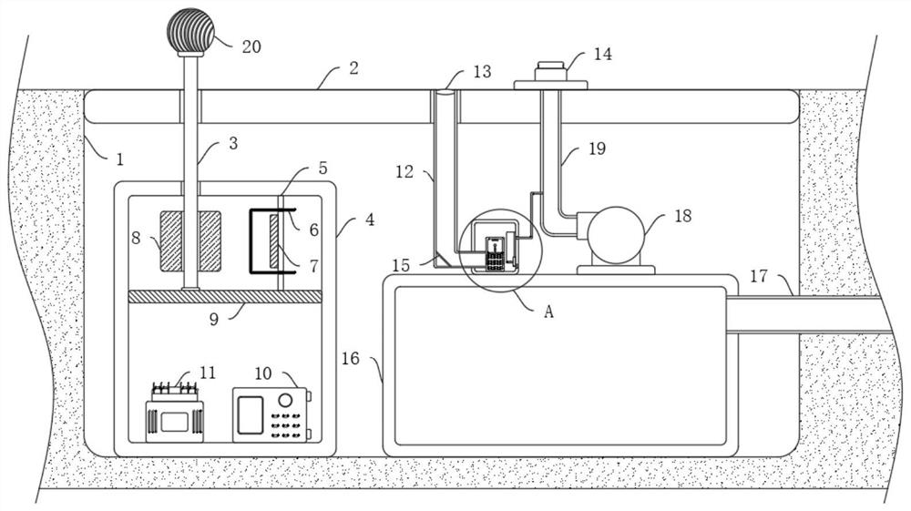
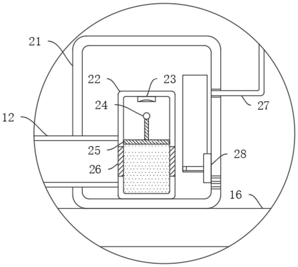
The present invention discloses a buried wind-heat combined park self-sprinkling system for cities in a plateau. The buried wind-heat combined park self-sprinkling system includes a foundation pit; the inner wall of the foundation pit is fixedly connected with a baffle, and the inner bottom of the foundation pit is fixedly connected with a mounting box and a water tank; the inside of the mountingbox is provided with a power supply mechanism; the power supply mechanism includes a partition plate fixedly connected to the inner wall of the mounting box; the upper wall of the partition plate is rotatably connected with a rotating rod by a bearing; the rotating rod is fixedly connected with a powerless wind ball after passing through the side wall of the baffle; the side wall, located in the mounting box, of the rotating rod is fixedly sleeved with a permanent magnet; the inner top of the mounting box and the upper wall of the partition plate are jointly and fixedly connected with a vertical plate; the side wall of the vertical plate is fixedly connected with a fixed magnetic plate; and the side wall of the vertical plate is fixedly spliced with a lead frame. By using the buried wind-heat combined park self-sprinkling system, the phenomenon that plants die due to water storage may be avoided, the manpower is greatly saved, the work efficiency is increased, in addition, electric energy and water resources are saved, and the buried wind-heat combined park self-sprinkling system conforms to the concept of environment-friendly cities.

Description

Technical field [0001] The invention relates to the technical field of park sprinklers, in particular to an underground self-sprinkling system used in plateau cities with combined wind and heat. Background technique [0002] The modern park generally refers to the public area built and operated by the government as a natural viewing area and for the public to rest and play. Because there are generally more green plants in the park, the air is fresh, and it is very popular with people. Everyone has free time. Willing to relax in the park. [0003] However, since green plants are planted, they must be watered, especially in some plateau cities, where the air is dry and the temperature is higher, and plants have a greater demand for water. If the plant’s demand for water cannot be met, then Plants in the park are prone to drought and die. On the one hand, it affects the aesthetics of the city. On the other hand, people need to replace dead plants, causing unnecessary trouble. The exi...

Claims


Application Information

Patent Timeline
IPC IPC(8): A01G25/02A01G25/16F03D9/11F03D9/43
CPCA01G25/02A01G25/16F03D9/11F03D9/43Y02B10/30Y02E10/72Y02E10/728Y02E70/30Y02P60/12
Inventor 江勇
Owner 江勇
Learn More