Anti-blocking rubber forming device

A rubber molding and rubber molding machine technology, applied in transportation and packaging, dispersed particle filtration, application, etc., can solve the problems of increasing the labor intensity of operators, affecting the continuity of the molding device, and lacking a fast feeding mechanism, and reducing labor. Strength, safe and convenient use, and the effect of reducing the burden

Inactive Publication Date: 2020-09-18
刘理仁
View PDF5 Cites 1 Cited by
  • Summary
  • Abstract
  • Description
  • Claims
  • Application Information

AI Technical Summary

Problems solved by technology

[0003] However, due to the lack of a corresponding fast feeding mechanism in the rubber molding machines currently on the market, when adding strips of rubber to the mold, it is still necessary to manually place the strips of rubber into the mold one by one, and the rubber is added to the mould. The process of mold operation is cumbersome and inefficient, which increases the labor intensity of operators and reduces productivity
The present invention belongs to an improved invention, and is a further improvement on the applicant's previous application, especially designed for the problem that the multi-layer activated carbon filter in the deodorization box is prone to clogging after time use, when the activated carbon filter is clogged It is often necessary to stop the machine for cleaning, which affects the continuity of the molding device and is not conducive to improving its continuous use rate.

Method used


Image

  • Anti-blocking rubber forming device
  • Anti-blocking rubber forming device
  • Anti-blocking rubber forming device

Examples


Embodiment

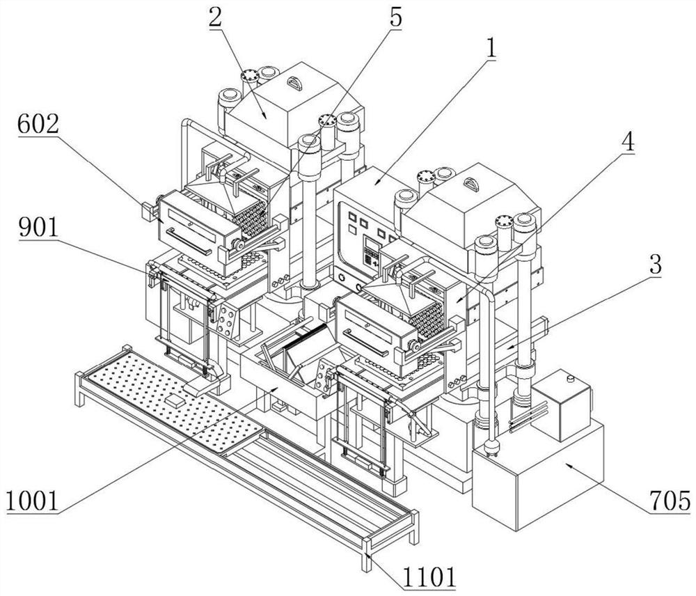
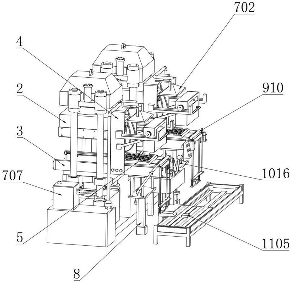
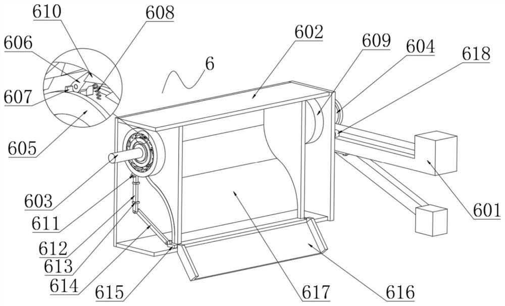
[0035] Example: such as Figure 1-10An anti-blocking rubber molding device shown includes a rubber molding machine control box 1, an equidistant feeding mechanism 6, an exhaust gas treatment mechanism 7, a mold cleaning mechanism 9, a finished product collection mechanism 10, a fast moving mechanism 11, and an exhaust gas treatment mechanism. The side wall of the deodorization box 707 in 7 is fixedly connected with a plurality of electric cleaning push rods 710, the quantity of the electric cleaning push rods 710 is the same as that of the activated carbon filter screen 708, and the output rod of each electric cleaning push rod 710 is fixedly connected with a brush Plate 711, the lower end of the brush plate 711 is fixedly connected with a brush filament 712, and the side wall of the deodorization box 707 is positioned at the lower side and the upper side of the activated carbon filter screen 708, and an inlet pressure sensor 713 and an outlet pressure sensor 714 are respective...


PUM


Abstract

The invention discloses an anti-blocking rubber forming device which comprises a rubber forming machine control box, an equidistant feeding mechanism, a tail gas treatment mechanism, a mold clearing mechanism, a finished product collecting mechanism and a quick moving mechanism. The side wall of a deodorizing box in the tail gas treatment mechanism is fixedly connected with multiple electric clearing push rods, and the number of the electric clearing push rods is equal to that of activated carbon filtering screens. An output rod of each electric clearing push rod is fixedly connected with a brush plate, and the lower ends of the brush plates are fixedly connected with brush wires. An inlet pressure sensor and an outlet pressure sensor are arranged at the positions, on the lower sides and the upper sides of the activated carbon filtering screens, of the side wall of the deodorizing box correspondingly. A foreign matter collecting box is arranged on the side wall of the side, opposite tothe electric clearing push rods, of the deodorizing box, and the outer wall of the foreign matter collecting box is fixedly connected with multiple matched electric push rods; and an output rod of each matched electric push rod is fixedly connected with an opening and closing plate, each opening and closing plate is located above the corresponding activated carbon filtering screen, and the opening and closing plates can be inlaid on the side walls of the deodorizing box.

Description

technical field [0001] The invention relates to the technical field of rubber molding, in particular to an anti-blocking rubber molding device. Background technique [0002] The rubber molding machine is currently the most widely used rubber material molding equipment. The mixed strip rubber is directly put into the open mold cavity, and then it is sent to the flat vulcanization press after the mold is closed. Heating, the rubber material is vulcanized and formed under the action of heating and pressure; [0003] However, due to the lack of a corresponding fast feeding mechanism in the rubber molding machines currently on the market, when adding strips of rubber to the mold, it is still necessary to manually place the strips of rubber into the mold one by one, and the rubber is added to the mould. The process of mold operation is cumbersome and inefficient, which increases the labor intensity of operators and reduces productivity. The present invention belongs to an improv...

Claims


Application Information

Patent Timeline
Patent Type & Authority Applications(China)
IPC IPC(8): B29C43/02B29C43/34B29C43/32B29C33/72B29C43/50B29C35/02B01D46/00B01D46/12B01D46/44B01D53/18B01D53/04B29L7/00
CPCB29C43/02B29C43/34B29C43/32B29C33/72B29C43/50B29C35/02B01D46/12B01D46/0086B01D46/446B01D53/18B01D53/04B29C2033/727B29C2043/503B29L2007/002B01D46/62
Inventor 刘理仁
Owner 刘理仁
Why Eureka
Try Eureka