Concrete construction device and method

A construction device and construction method technology, applied in earthwork drilling, foundation structure engineering, drilling equipment, etc., can solve the problems of different degrees of bending of steel bars, uneven distribution of steel bar skeletons, and insufficient pull-out resistance of concrete piles, etc., to achieve Easy to adjust and good pull-out resistance

Active Publication Date: 2020-09-18
ZHEJIANG XINZHONGYUAN CONSTR
View PDF8 Cites 1 Cited by
  • Summary
  • Abstract
  • Description
  • Claims
  • Application Information

AI Technical Summary

Problems solved by technology

[0005] However, through the extrusion and expansion of dry hard concrete, the main reinforcement at the bottom of the reinforcement cage will be spread out. Different reinforcements will have different extrusion and expansion forces, resulting in different degrees of bending of the reinforcement, so that the reinforcement in the expansion head The skeleton is not evenly distributed. At the same time, only the outer layer of the enlarged head is equipped with steel bars and the interior is empty. There is no good skeleton to play a fixed role. The strength of the enlarged head is not high enough, and the pull-out capacity of the concrete pile is not strong enough.

Method used


Image

  • Concrete construction device and method
  • Concrete construction device and method
  • Concrete construction device and method

Examples


Embodiment 1

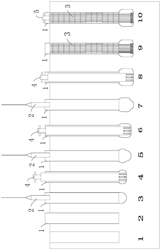
[0059] refer to figure 1 , is a concrete construction device disclosed in the present invention, comprising an outer pipe 1 , an inner rammer 2 , a reinforcement cage 3 , a soil expander 4 , a reinforcement expander 5 , an expanded steel ball 6 and an adjustment rod 7 . The outer pipe 1 is a steel pipe or a cement pipe with a designed length, and in this embodiment, a cement pipe is used; the material of the inner tamper 2 can be cast steel, and the weight of the inner tamper 2 can be adjusted by adjusting the length of the inner tamper 2. The upper part of the inner rammer 2 can be connected with a crane by a steel cable, and the inner rammer 2 is lifted by the crane.

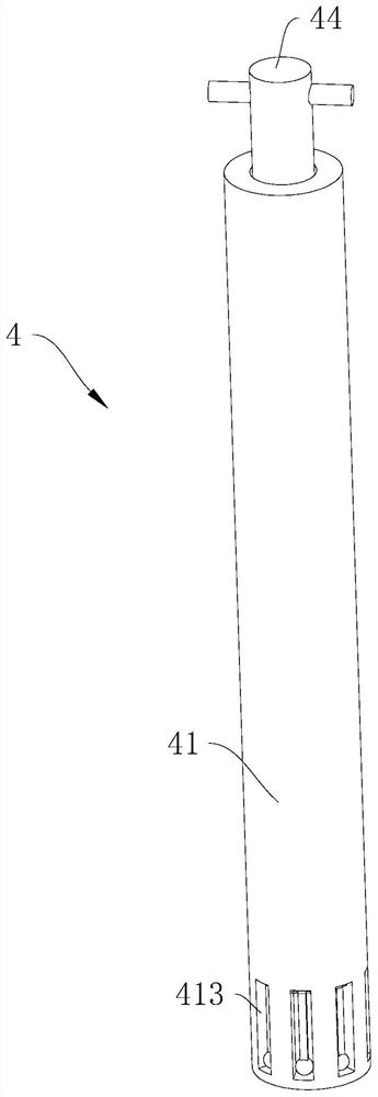
[0060] refer to figure 2 with image 3 The soil expander 4 includes a casing 41, a hammer 42, a push rod 43 and a drive rod 44. The casing 41 is provided with a sliding chamber 411 with an upper opening, and the bottom of the sliding chamber 411 is vertically provided with a limit post 412, and the driving ...

Embodiment 2

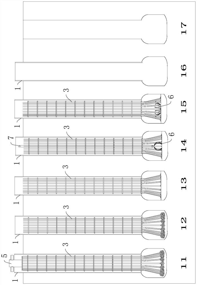
[0069] refer to Figure 9 The difference between this embodiment and Embodiment 1 is that the puller is a stay cord 732, there are several stay cords 732, and several stay cords 732 are arranged at interval angles along the circumferential direction of the slip sleeve 72, and one end of the stay cord 732 is fixed to the slip sleeve 72 , the other end of the stay rope 732 is fixed with the tie rope 63.

Embodiment 3

[0071] refer to figure 1 , a concrete construction method, the method adopts the above-mentioned concrete construction device, and the method comprises the steps of:

[0072] 1) Select the location where piling needs to be driven, and pre-dig the pile hole with the design depth at the pile location;

[0073] 2) sink the outer tube 1 into the pile hole;

[0074] 3) Put the inner rammer 2 into the outer tube 1, and expand the space at the bottom of the outer tube 1 through the free fall movement of the inner rammer 2 in the outer tube 1 until the bottom of the inner rammer 2 is located on the outer tube 1 A certain distance below is 17cm to 33cm in the present embodiment, and the weight and falling position of the internal rammer 2 are determined according to the actual soil quality;

[0075] 4) Put the expander 4 into the outer tube 1 as a whole, push and pull the drive rod 44 up and down, rotate the expander 4 at a certain angle every few times, until the drive rod 44 can slid...


PUM


Abstract

The invention relates to a concrete construction device. The concrete construction device comprises an outer pipe, an inner rammer, a steel reinforcement cage, a soil expander, a rib expander and an expansion steel bar ball, and further comprises a concrete construction method which comprises the following steps that 1) a pile hole is pre-excavated; 2) the outer pipe is sunk into the pile hole; 3)the inner rammer freely falls to expand and punch the bottom space of the outer pipe; 4) the soil expander is put into the outer pipe for soil expansion; 5) the soil expander is taken out, and the bottom space is expanded and punched through free falling of the inner rammer; 6) the step (4) and the step (5) are repeated to expand and punch an expanded head space; 7) the soil expander and the inner rammer are taken out, and the soil expander and the inner rammer are put into the steel reinforcement cage; 8) the rib expander is placed into the outer pipe for rib expansion; 9) a layer of cementis poured into the expanded head space; 10) the expansion steel bar ball is placed into the expanded head space, and a binding rope is pulled out; 11) the opened expansion steel bar ball is adjusted through an adjusting rod; 12) concrete is poured into the outer pipe to the top of a pile; and 13) the outer pipe is lifted out, and the dense concrete is vibrated. The construction method has the effect that the constructed pile is high in anti-pulling capacity.

Description

technical field [0001] The invention relates to the technical field of civil engineering, in particular to a concrete construction device and a construction method. Background technique [0002] Concrete construction is carried out in accordance with the requirements of the design drawings, making and binding steel bars, placing and fixing formwork, using raw materials that meet quality requirements, mixing, transporting, pouring, and curing according to the specified ratio, and at the same time carrying out the whole process of each link Quality control and inspection. Concrete is one of the most important civil engineering materials in contemporary times, and its application is extensive, such as concrete beams, concrete piles, concrete walls and so on. [0003] Reinforced concrete pile is a pile made of concrete with steel bar as the skeleton. It has been widely used in the foundation engineering of hydraulic construction, industrial construction, civil construction and ...

Claims


Application Information

Patent Timeline
Patent Type & Authority Applications(China)
IPC IPC(8): E02D5/38E02D5/44E21B10/26
CPCE02D5/38E02D5/385E02D5/44E02D2300/002E21B10/26
Inventor 宋丽娟叶剑波过良斌赵小林乐连欢沈志荣贺军
Owner ZHEJIANG XINZHONGYUAN CONSTR
Why Eureka
Try Eureka