
Rolling bearing fault detection method based on acoustic vibration signal fusion

A rolling bearing and signal fusion technology, which is applied in the testing of mechanical components, testing of machine/structural components, measuring devices, etc., can solve problems such as difficult to detect faults, low amplitude at fault frequency, low signal-to-noise ratio, etc., to improve accuracy Improve performance and diagnostic efficiency, solve the problem of low signal-to-noise ratio, and improve sensitivity

Active Publication Date: 2020-09-18
SHENYANG JIANZHU UNIVERSITY
View PDF7 Cites 7 Cited by
  • Summary
  • Abstract
  • Description
  • Claims
  • Application Information

AI Technical Summary

Problems solved by technology

However, the vibration signal is obtained through contact measurement, and the layout of the vibration sensor is limited by the environment, so it is not suitable for installation in a working environment with high temperature, high humidity and high corrosion, and the amplitude of the fault frequency is low, so it is difficult to detect weak faults , and the acoustic signal is obtained through non-contact measurement, which can improve the limitation of contact measurement of vibration signal, and has become a new research method in fault diagnosis
However, in the process of collecting acoustic signals, fault feature information is easily affected by background noise, resulting in low signal-to-noise ratio and insufficient diagnostic accuracy.

Method used


Image

  • Rolling bearing fault detection method based on acoustic vibration signal fusion
  • Rolling bearing fault detection method based on acoustic vibration signal fusion
  • Rolling bearing fault detection method based on acoustic vibration signal fusion

Examples


Embodiment Construction

[0035] The invention will be further described below in conjunction with the accompanying drawings and specific implementation examples.

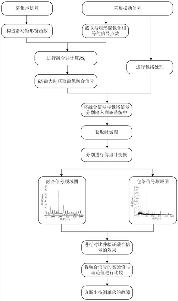
[0036] Such as figure 1 As shown, a rolling bearing fault detection method based on acoustic vibration signal fusion, including the following steps:

[0037] Step 1: Collect the vibration signal V' and the acoustic signal S' of the rolling bearing to be tested, and store them on the computer respectively; the sensor Q for collecting the vibration signal V' 1 Adsorbed on the bearing seat of the rolling bearing to be tested, the sensor Q that collects the acoustic signal S' 2 Installed on a plane 420mm from the end face of the bearing, and meet the sensor Q 2 The center point of is located on the axis of the bearing;

[0038] Step 2: Extract a segment containing N from the vibration signal V' v The vibration signal of consecutive signal points is taken as the vibration signal V to be detected, that is, V={V[u]|u=1,2,...,N v}; Extract a s...


PUM


Abstract

The invention provides a rolling bearing fault detection method based on acoustic vibration signal fusion, which comprises the following steps of: firstly, extracting a vibration signal and a sound signal of a rolling bearing to be detected, and establishing a sliding rectangular window function of the sound signal; secondly, by starting from a first signal point of a to-be-detected vibration signal, establishing a fusion signal after each time of movement by moving a rectangular window, solving a root-mean-square value and a mean-flexible value of the fusion signal to obtain a mean-slip value, and finding out an optimal fusion signal; and finally diagnosing a fault of a bearing to be detected by judging a value range of an approximate fault characteristic frequency where the optimal fusion signal is located. According to the invention, the problems that the vibration sensor arrangement is limited, the amplitude at the fault characteristic frequency is low and the like are solved, meanwhile, the problem that the signal-to-noise ratio is low due to the fact that sound signals are affected by background noise is solved, weak faults of a rolling bearing can be accurately recognized, the diagnosis accuracy and diagnosis efficiency are improved, and a good effect is achieved in rolling bearing state monitoring.

Description

technical field [0001] The invention relates to the technical field of bearing fault diagnosis, in particular to a rolling bearing fault detection method based on acoustic vibration signal fusion. Background technique [0002] Rolling bearings are one of the most widely used components in rotating machinery, and are widely used in important fields such as machining, metallurgy, chemical industry and aviation. Because rolling bearings are often in high-temperature, high-speed and heavy-load working environments, rolling bearings are easily damaged. Once they fail and are not detected in time, it will cause machine failure and unexpected shutdown, resulting in huge economic losses and even threats. to the personal safety of workers. Therefore, in rotating machinery, fault diagnosis of rolling bearings plays a vital role. [0003] The vibration signals of rolling bearings contain a lot of information and are easy to obtain. They have been widely used in the fault diagnosis of...

Claims


Application Information

Patent Timeline
Patent Type & Authority Applications(China)
IPC IPC(8): G01M13/045
CPCG01M13/045
Inventor 石怀涛李阳阳白晓天李献文李思慧
Owner SHENYANG JIANZHU UNIVERSITY
Learn More