High-precision accelerometer temperature compensation method

An accelerometer and temperature compensation technology, applied in the field of inertial measurement, can solve the problems of measurement inaccuracy of accelerometer components, changes in installation errors, and inability to quantitatively measure deformation, and achieve the effect of shortening time and improving efficiency

Active Publication Date: 2020-09-18
BEIJING AEROSPACE TIMES OPTICAL ELECTRONICS TECH
View PDF11 Cites 4 Cited by
  • Summary
  • Abstract
  • Description
  • Claims
  • Application Information

AI Technical Summary

Problems solved by technology

[0003] To achieve accurate temperature compensation, an accurate temperature error model of the accelerometer must be established. The influence of temperature on the output of the accelerometer components in the inertial navigation system is mainly manifested in two aspects: On the one hand, when the system is working normally, the internal temperature change of the system causes The scale factor and zero bias of the accelerometer itself change, which leads to inaccurate measurement of the accelerometer components; Causes changes in installation errors and affects the measurement accuracy of accelerometer components
For medium and low-precision inertial navigation systems, the effect of temperature compensation on zero offset and scale factor is the best, and the accuracy can also meet the requirements. However, for high-precision inertial navigation systems, if the test equipment produces a deformation of 2 arc seconds , which is equivalent to the accelerometer introducing 1*10 -5 g error, therefore, the deformation of the installation caused by the deformation of the structure body and the test tool cannot be ignored, but it is impossible to quantitatively measure these deformations in practice, which requires the design of a high-precision temperature compensation method. Eliminate errors caused by installation deformation

Method used


Image

  • High-precision accelerometer temperature compensation method
  • High-precision accelerometer temperature compensation method
  • High-precision accelerometer temperature compensation method

Examples


Embodiment

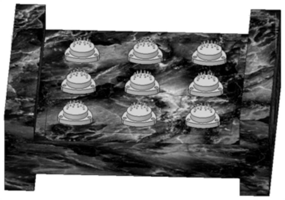
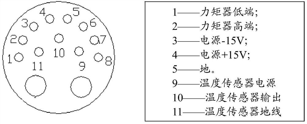
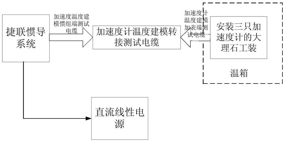
[0119] Mount an accelerometer with temperature output on an accelerometer ( figure 2 ) special marble tooling ( figure 1 ), place it in a temperature-controlled test box with a marble slab, and connect it to the external strapdown inertial navigation through a cable (the schematic diagram is as follows image 3 ), close the door of the temperature control test chamber, follow the temperature curve ( Figure 4 ) Set the control program of the temperature control test box, start the temperature control test box to start cooling, the temperature box is kept at a low temperature of -40°C for 3 hours, so that the temperature of the three accelerometer components is consistent with the temperature of the temperature control test box, turn on the power of the product, and start the strapdown During the temperature modeling test, the output pulse of the accelerometer is collected through the external strapdown inertial navigation system. The temperature of the thermostat is raised a...


PUM


Abstract

The invention discloses a high-precision accelerometer temperature compensation method, and belongs to the field of inertial measurement. The quartz flexible accelerometer is composed of a gauge outfit assembly and a servo circuit assembly. The change of the ambient temperature enables the physical parameters of various materials in the quartz flexible accelerometer to change, thereby generating an influence on the output of the accelerometer. According to the marble tool single-meter-level two-way variable temperature modeling method, the influence of deformation of a strapdown inertial navigation combination body and a test tool on the precision of an accelerometer in the previous temperature modeling process is eliminated, and the precision that the zero-bias stability 3sigma of the accelerometer is smaller than or equal to 0.05 mg under the full-temperature condition is achieved.

Description

technical field [0001] The invention relates to an accelerometer temperature compensation method for high-precision and small-volume strapdown inertial navigation used for navigation and guidance, which belongs to the field of inertial measurement. Background technique [0002] The quartz flexible accelerometer is one of the core sensitive elements of the strapdown inertial navigation system, and its accuracy directly affects the attitude, speed and positioning accuracy of the navigation system. Factors such as ambient temperature, vibration, magnetic field, and air pressure will all affect the accuracy of the accelerometer, and the impact of ambient temperature is particularly important. Therefore, the influence of ambient temperature needs to be considered when designing the inertial navigation system. At present, domestic measures to improve the influence of temperature on accelerometers are mainly temperature control or temperature compensation. The temperature control...

Claims


Application Information

Patent Timeline
Patent Type & Authority Applications(China)
IPC IPC(8): G01P15/02G01P1/00
CPCG01P15/02G01P1/006
Inventor 郝金艺赵博辉仇立伟石利利吴立秋江浩
Owner BEIJING AEROSPACE TIMES OPTICAL ELECTRONICS TECH
Why Eureka
Try Eureka