High-speed vacuum positioning centrifuge

A centrifuge and vacuum technology, applied in the field of centrifuges, can solve the problems of air resistance affecting the centrifugation effect, long waiting time, difficult high-speed centrifugation of centrifuges, etc., to achieve the effects of heat avoidance, convenient access, and noise reduction

Inactive Publication Date: 2020-09-22
苏州创新通用色谱仪器有限公司
View PDF11 Cites 0 Cited by
  • Summary
  • Abstract
  • Description
  • Claims
  • Application Information

AI Technical Summary

Problems solved by technology

The centrifuge is more convenient to use, but the waiting time is too long. At present, there are centrifuges on the market that are used with automatic grippers. This type of centrifuge often uses horizontal rotors, but the horizontal rotors often have a lot of air when they rotate at high speed. The resistance affects the centrifugation effect, which makes it difficult for this type of centrifuge to perform high-speed centrifugation, and causes this type of centrifuge to have greater noise and heat. Based on this, the present invention designs a high-speed vacuum positioning centrifuge to solve the above problems

Method used


Image

  • High-speed vacuum positioning centrifuge
  • High-speed vacuum positioning centrifuge
  • High-speed vacuum positioning centrifuge

Examples


Embodiment 1

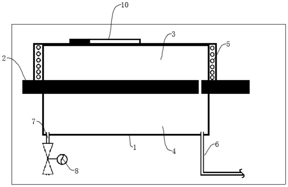
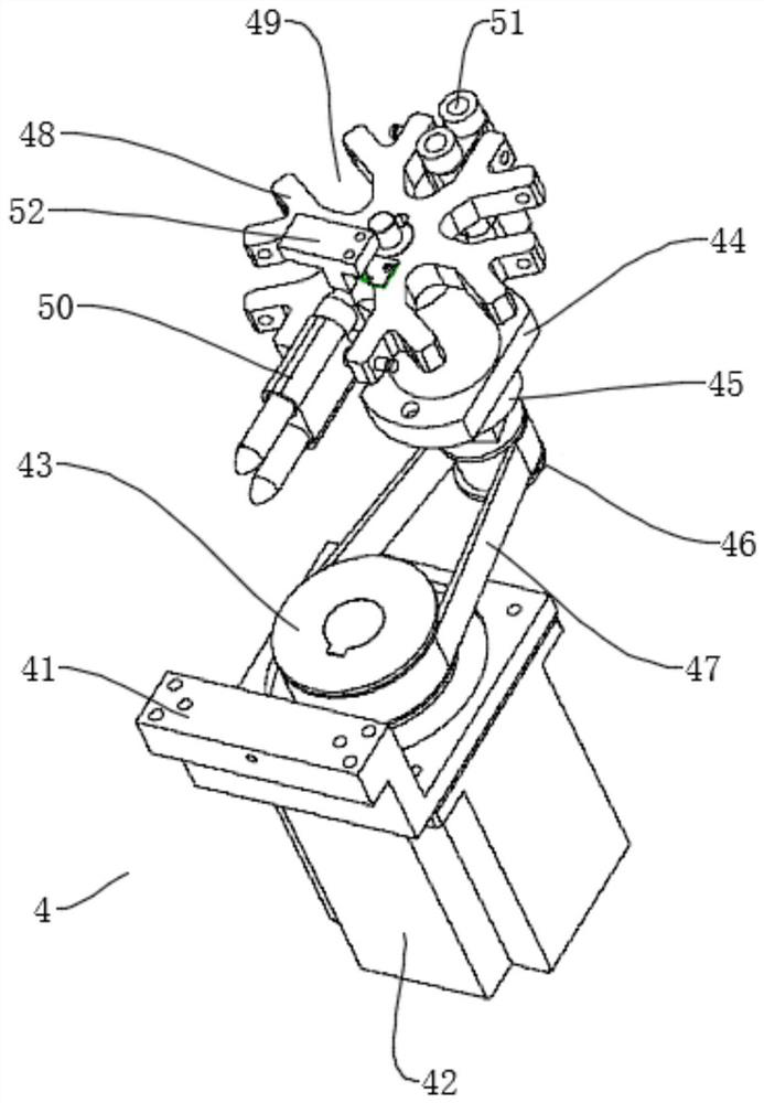
[0031]Embodiment 1: The large synchronous wheel 43 and the synchronous belt 47 are driven by the servo motor 42, and then the small synchronous wheel 46 and the centrifugal rotor 48 on it are driven, and the U-shaped card slot 49 is positioned by the photosensitive position sensor 52, and the centrifuge runs Before, the refrigeration compressor in the refrigeration box 502 starts to work first, so that the refrigeration pipe 501 cools down the rotor chamber 3, and starts to run the centrifuge after reaching the target temperature. move to seal), and at the same time, the lower electromagnetic valve 8 is closed, so that the centrifuge housing 1 is in a sealed state, then the vacuum pump starts to work, and the centrifugal rotor 48 starts to increase the speed at the same time, and rises to the set speed when the vacuum reaches the standard, and maintains The set time, after reaching the set time, the servo motor 42 controls the centrifugal rotor 48 to decelerate, when the speed ...

Embodiment 2

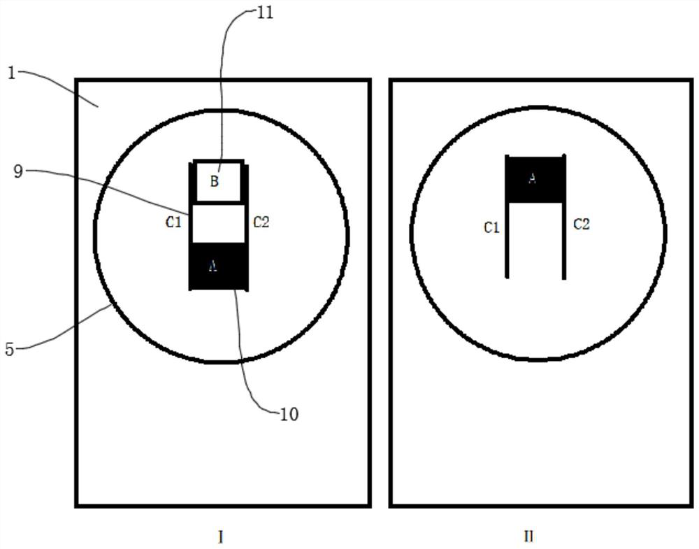
[0032] Embodiment two: if cooperate manipulator E (and manipulator E is the equipment that carries in centrifuge shell 1 in the prior art, for example TG16-WS centrifuge) realize automatic operation, then as Image 6 As shown in middle I, after the slider completely leaves the E part, the manipulator will grab the centrifuge tubes in the 1 and 2 holes in the E range, and then the servo motor will drive the rotor to move to the position of II, 3, 4. The two centrifuge tubes are in the E range, and the manipulator will carry out the grabbing activity again. After grabbing the centrifuge tubes in the 3rd and 4th holes, the servo motor will continue to move, and this cycle will continue until all 12 centrifuge tubes are grabbed, and the manipulator will cooperate with the centrifuge. The operation of the instrument for tube placement is also the same as that described in Example 1.


PUM


Abstract

The invention discloses a high-speed vacuum positioning centrifuge in the technical field of centrifuges. The high-speed vacuum positioning centrifuge comprises a centrifuge shell, a partition plate is transversely mounted in an inner cavity of the centrifuge shell, and one end of the partition plate is not in contact with the side wall of the centrifuge shell; the partition plate divides the inner cavity of the centrifuge shell into an upper rotor chamber and a lower motor chamber, and a centrifugal mechanism is installed in an inner cavity of the motor chamber, and a refrigerating mechanismis installed on the outer wall of the centrifuge shell, and a vacuum pipe is installed on one side of the bottom of the centrifuge shell. A vacuum environment is provided for the rotor chamber in thecentrifugal process, and on one hand, vibration caused by friction between a centrifugal rotor and air during centrifugation can be eliminated through the vacuum environment; on the other hand, noisegenerated by operation of a servo motor can be greatly reduced; and multiple circles of refrigeration pipes are wound outside the rotor chamber, the refrigeration effect is achieved, and meanwhile, due to the fact that the interior of the rotor chamber is in a vacuum state, heat can be rapidly conducted, and the moisture condensation phenomenon is effectively avoided.

Description

technical field [0001] The invention relates to the technical field of centrifuges, in particular to a high-speed vacuum positioning centrifuge. Background technique [0002] A centrifuge is a machine that uses centrifugal force to separate components in a mixture of liquid and solid particles or liquid and liquid. The centrifuge is mainly used to separate the solid particles in the suspension from the liquid, or to separate two different densities and immiscible liquids in the emulsion (such as separating cream from milk); it can also be used to remove Liquid in wet solids, such as drying wet clothes with a washing machine; special ultra-speed tube separators can also separate gas mixtures of different densities; using the characteristics of different sedimentation velocities of solid particles of different densities or particle sizes in liquids, some sedimentation Centrifuges can also classify solid particles by density or size. [0003] Centrifuges are often used for th...

Claims


Application Information

Patent Timeline
Patent Type & Authority Applications(China)
IPC IPC(8): B04B15/08B04B15/02B04B9/02B04B9/08B04B7/02
CPCB04B15/08B04B15/02B04B9/02B04B9/08B04B7/02
Inventor 张业平刘继宇
Owner 苏州创新通用色谱仪器有限公司
Why Eureka
Try Eureka