
Variable-depth chamfering machining method for side edge of magnetic pole of spiral fan

A processing method and technology of helical fan, applied in metal processing, metal processing equipment, metal processing mechanical parts, etc., can solve the problem of inability to provide variable depth chamfering graphics, the difficulty of precise processing of variable depth chamfering on the side of the magnetic pole of the helical fan, etc. problems, to achieve the effect of reducing asymmetry, improving accuracy, and improving consistency

Active Publication Date: 2020-09-22
CHINA INSTITUTE OF ATOMIC ENERGY
View PDF7 Cites 0 Cited by
  • Summary
  • Abstract
  • Description
  • Claims
  • Application Information

AI Technical Summary

Problems solved by technology

[0003] For the magnetic field of the spiral fan, the side of the magnetic pole is often composed of multiple disconnected segments. Most of the current mechanical design software, such as solidwork, only provides the function of generating chamfering graphics with a fixed depth on the side of the magnetic pole, but cannot provide chamfering with variable depths. The generation of graphics; while modern machine tool processing often needs to be processed according to the three-dimensional mechanical model diagram, it is difficult to accurately process the variable depth chamfering on the side of the spiral fan magnetic pole

Method used


Image

  • Variable-depth chamfering machining method for side edge of magnetic pole of spiral fan
  • Variable-depth chamfering machining method for side edge of magnetic pole of spiral fan
  • Variable-depth chamfering machining method for side edge of magnetic pole of spiral fan

Examples


Embodiment

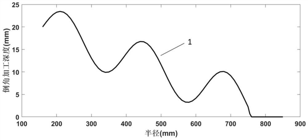
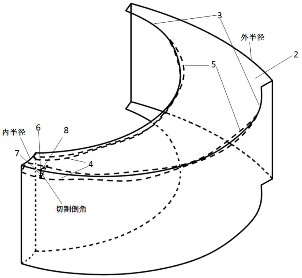
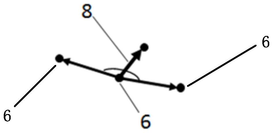
[0053] A 230MeV superconducting proton cyclotron adopts a four-fan spiral fan magnetic pole structure, with a total of 8 magnetic poles. The inner radius of each magnetic pole is 160mm, the outer radius is 850mm, and the two sides are spiral. The physical design requires magnetic poles The magnetic field is corrected by side chamfering, and the bevel angle of chamfering is 45 degrees. figure 2 As shown, the physical calculation gives a curve of chamfer depth changing with radius as figure 1 As shown, it is used for the processing of magnetic pole chamfering. 3D modeling software such as Solidwork cannot accurately give the cutting model of the chamfer depth changing with the radius. It is necessary to borrow the Boolean operation of the software to generate the cutting model. The steps are as follows:

[0054] Step 1. First calculate a shape body with variable depth chamfering on the side of the spiral fan magnetic pole as the cutting body;

[0055] Specifically:

[0056] ...


PUM


Abstract

The invention discloses a variable-depth chamfering machining method for the side edge of a magnetic pole of a spiral fan. The variable-depth chamfering machining method comprises the following stepsthat firstly, a shape body of a variable-depth chamfer of the side edge of the magnetic pole of the spiral fan is worked out to serve as a cutting body; difference set operation of Boolean operation is performed on the cutting body and the shape body, to be subjected to variable-depth chamfering, of the magnetic pole of the spiral fan, so that cutting of the cutting body on the side edge of the magnetic pole of the spiral fan is completed, and a spiral fan magnetic pole three-dimensional model after chamfering processing is generated after cutting; and spiral fan magnetic pole three-dimensional model after chamfering processing is imported into machine tool machining software so as to complete a machining program. According to the variable-depth chamfering machining method, by establishingthe variable-depth chamfering cutting body and establishing a bilinear angular bisector model, the variable-depth chamfering machining problem of the side edge of the magnetic pole of the spiral fanin a cyclotron is solved, a high-precision variable-depth chamfering cutting model is achieved through the Boolean operation function of the mechanical software, the consistency of chamfering machining of multiple magnets is improved, the asymmetry of a magnetic field is reduced, and the overall performance of an accelerator is improved.

Description

technical field [0001] The invention belongs to the technical field of cyclotrons, and in particular relates to a method for chamfering the sides of spiral fan magnetic poles with variable depth. Background technique [0002] In a superconducting proton cyclotron, the magnetic field is very saturated. In order to reduce the local magnetic field saturation, the physical design requires that the magnetic field be corrected by chamfering the side of the magnetic pole; for different radii, the amount of the corrected magnetic field is different, and the physical calculation will be Give a curve of chamfer depth changing with radius, which is used for the processing of magnetic pole chamfer. [0003] For the magnetic field of the spiral fan, the side of the magnetic pole is often composed of multiple disconnected segments. Most of the current mechanical design software, such as solidwork, only provides the function of generating chamfering graphics with a fixed depth on the side ...

Claims


Application Information

Patent Timeline
IPC IPC(8): B23Q15/04
CPCB23Q15/04
Inventor 李明张天爵崔涛王川林军
Owner CHINA INSTITUTE OF ATOMIC ENERGY
Learn More