
Surface microstructural array with self-transportation performance and forming method thereof

A microstructure array and molding method technology, applied in 3D object support structures, manufacturing tools, additive manufacturing, etc., can solve the problems of low molding efficiency, difficulty in forming microstructures on functional surfaces, and low condensation efficiency on superhydrophobic functional surfaces. The effect of reducing molding time, improving molding accuracy and molding quality, and improving condensation efficiency

Inactive Publication Date: 2020-09-22
CHANGSHA UNIVERSITY OF SCIENCE AND TECHNOLOGY
View PDF0 Cites 4 Cited by
  • Summary
  • Abstract
  • Description
  • Claims
  • Application Information

AI Technical Summary

Problems solved by technology

[0003] Aiming at the above-mentioned technical problems such as the low condensation efficiency of the existing superhydrophobic functional surface, the difficulty in molding the microstructure of the functional surface, and the low molding efficiency, the present invention aims to provide a surface microstructure with self-transportation performance for resin-based pipes or devices. Structural array and its forming method

Method used


Image

  • Surface microstructural array with self-transportation performance and forming method thereof
  • Surface microstructural array with self-transportation performance and forming method thereof
  • Surface microstructural array with self-transportation performance and forming method thereof

Examples


Embodiment Construction

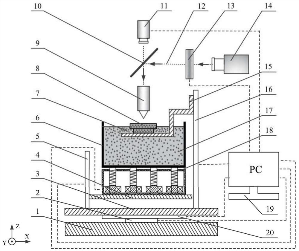
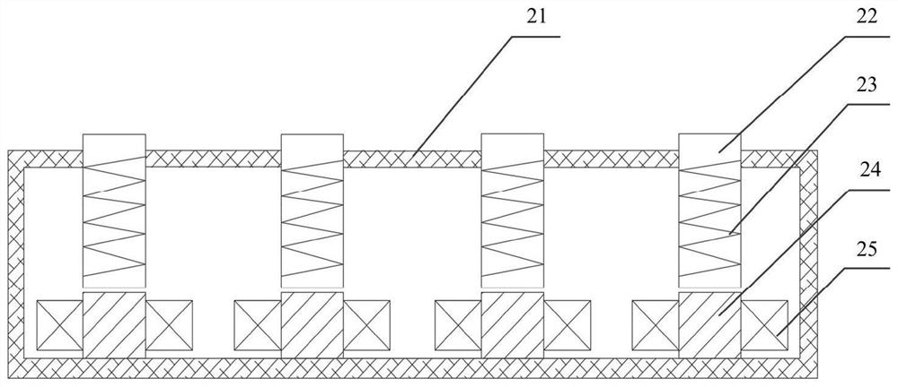
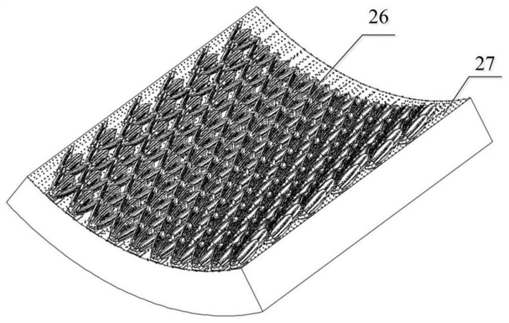
[0021] See attached Figure 1~4 , the single microstructure of the self-transporting surface microstructure array is a shark scale imitation structure 28, which is a triangular protrusion, made of photosensitive resin 7, with a total length of 13.6 µm in the transverse direction and a total length of 10.2 µm in the longitudinal direction , and the total length is 6.2µm; the lateral distance between two adjacent microstructures is 7.8µm, and the vertical distance is 4.2µm; the tail of the raised microstructure is inclined upward about 26° relative to the inner wall of the pipe or the surface of the device; on the surface of the microstructure, Nanoparticles 17 are distributed to form a micro / nano composite structure with the sharkskin structure 28 ; a plurality of the above composite structures are evenly distributed on the target surface 27 of the molded part to form a surface microstructure array 26 .

[0022] The forming method of the surface microstructure array 26 with self...


PUM


Abstract

The invention discloses a surface microstructural array with self-transportation performance and a forming method thereof. A single microstructure of the surface microstructural array is a shark scaleimitating structure, the shark scale imitating structures are triangular protrusions and are made from photosensitive resin, and the size is in micron order. Nano particles are distributed on the surfaces of the microstructures, and micro / nano composite structures are formed by the nano particles and the shark scale imitating structures. Multiple composite structures are evenly distributed on thetarget face of a formed part, and the surface microstructural array is formed. According to the forming method of the microstructural array, the surface microstructural array is prepared through an electromagnetically assisted vibrating face projection micro-stereoscopic photoetching system according to certain steps. According to the surface microstructural array, automatic transportation of condensate liquid drops can be achieved, and the condensation efficiency is improved. According to the forming method, by means of high-frequency vibration of an electromagnetic assisted vibration device, nano particle aggregations can be reduced, even distribution of the nano particles is achieved, and the forming precision and the forming quality are improved. A forming system moving platform can do horizontal rectilinear motion in the Y-axis direction and the X-axis direction, the area of a forming layer face and the size of the formed part are expanded, the forming time is shortened, and theforming efficiency is improved.

Description

technical field [0001] The invention belongs to the technical field of surface modification and 3D printing molding, and in particular relates to a microstructure array on the inner wall of a biological culture dish with antibacterial properties and a molding method thereof. Background technique [0002] In recent years, with the continuous improvement of energy-saving emission reduction and sustainable development requirements in the industrial production process, the importance of condensate collection and recycling in the fields of chemical industry, metallurgy, machinery and other fields has become increasingly prominent. According to the different surface wettability, the condensation process is mainly divided into film condensation and drop condensation, in which the heat transfer rate of the latter is several times or even ten times that of the former. Literature research shows that constructing functional surfaces with superhydrophobic properties on the surface of pi...

Claims


Application Information

Patent Timeline
IPC IPC(8): B29C64/124B29C64/20B29C64/386B29C64/264B29C64/30B29C64/245B29C64/379B29C64/232B29C64/236B33Y30/00B33Y40/00B33Y40/20B33Y50/00B33Y80/00
CPCB33Y30/00B33Y40/00B33Y50/00B33Y80/00B29C64/124B29C64/20B29C64/232B29C64/236B29C64/245B29C64/264B29C64/30B29C64/379B29C64/386B33Y40/20
Inventor 唐昆李典雨陈紫琳易香怀张明军毛聪尹来容
Owner CHANGSHA UNIVERSITY OF SCIENCE AND TECHNOLOGY
Learn More