Fly ash cooled pellet ball press machine

A ball press and ball machine technology, applied in the direction of presses, material forming presses, manufacturing tools, etc., can solve the problem of low ball forming rate of ball presses, reduce the probability of loose or unextruded molding, improve Squeeze effect, the effect of prolonging the squeezing time

Active Publication Date: 2020-09-22
CHONGQING ZHONGZHA METALLURGY RENEWABLE RESOURCESCO
View PDF14 Cites 0 Cited by
  • Summary
  • Abstract
  • Description
  • Claims
  • Application Information

AI Technical Summary

Problems solved by technology

[0004] The object of the present invention is to provide a dedusting and cooling ball briquetting machine to solve the problem that the ball forming rate of the existing briquetting machine is not high

Method used


Image

  • Fly ash cooled pellet ball press machine
  • Fly ash cooled pellet ball press machine
  • Fly ash cooled pellet ball press machine

Examples


Embodiment 1

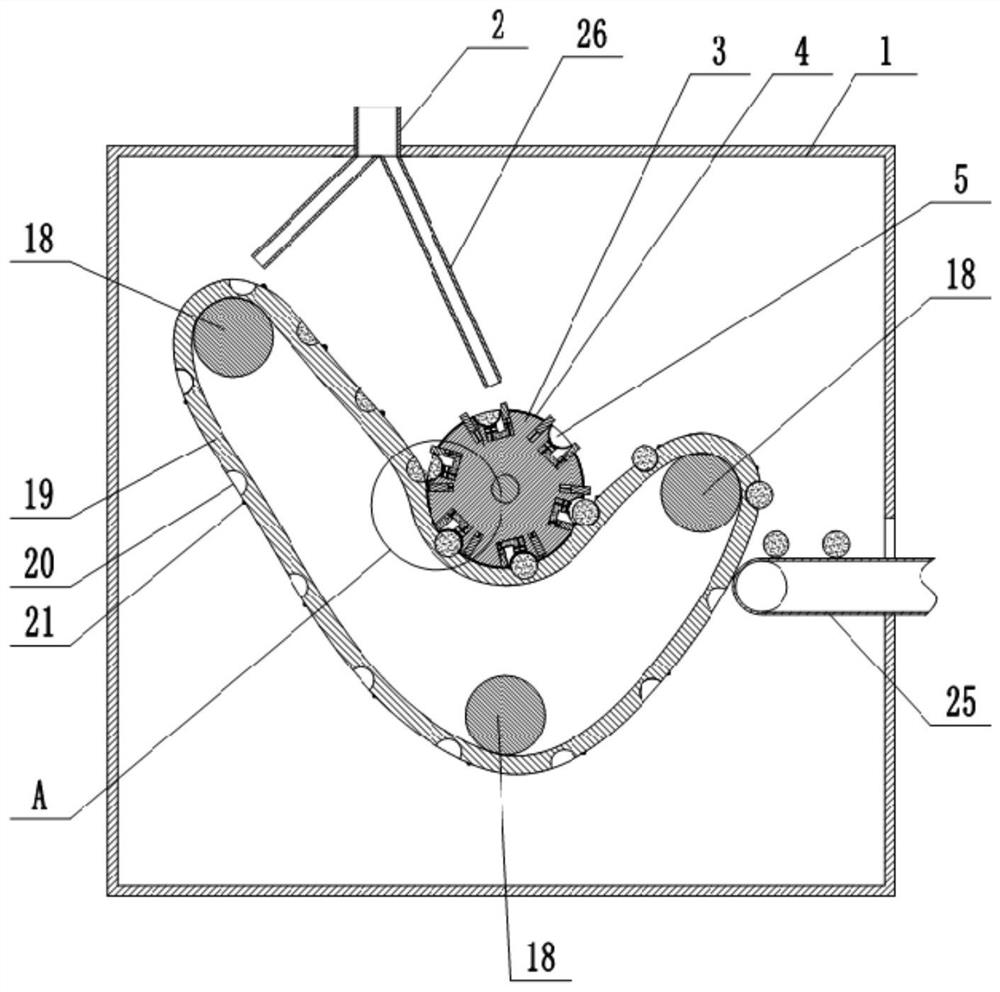
[0036] The dedusting ash cooling ball briquetting machine is mainly composed of a box body 1, a feed inlet 2, a driving roller 3, a roller sleeve 4, a first ball socket 5, a pushing unit, a driven roller 18, a transmission belt 19, and a driving unit. combined with figure 1As shown, the feed port 2 is set on the left side of the top of the box body 1, and the cross section of the feed port 2 is a long rectangular shape. There are two feed branch pipes 26 connected to the bottom of the feed port 2, and one of the feed branch pipes 26 The outlet end is aligned with the upper left part of the transmission belt 19, and the outlet end of the other feeding branch pipe 26 is positioned at the upper left part of the driving roller 3. The cross-sections of the two feeding branch pipes 26 are also elongated rectangles and extend along the width direction of the transmission belt 19 . An intermittent conveyor (not shown in the figure) is installed above the casing 1, and the intermitten...

Embodiment 2

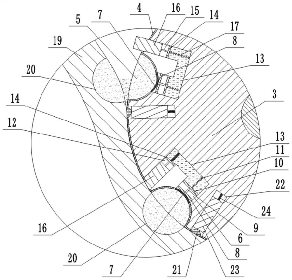
[0052] The difference between this embodiment and Embodiment 1 is: in this embodiment, in combination with the attached figure 2 As shown, the driving roller 3 is also provided with a plurality of second sliding ports 22, the second sliding ports 22 correspond to the first sliding ports one by one, and the first sliding ports can be connected with the second sliding ports 22 to form a channel. The second sliding port 22 is slidably and sealedly connected with a protective plate 23, and one end of the protective plate 23 is fixedly connected with a third elastic member 24, and the third elastic member 24 is fixedly connected with the bottom end of the first sliding port, and the third elastic member 24 It is a compression spring; the other end of the protective plate 23 passes through the first sliding opening and stretches out the roller sleeve 4 . When the third elastic member 24 is not compressed, the distance of the protective plate 23 above the roller sleeve 4 is 0.5-1.5 ...


PUM


Abstract

The invention relates to the technical field of metal smelting, and discloses a fly ash cooled pellet ball press machine. The fly ash cooled pellet ball press machine comprises a box body, a feeding port and a driving roller, wherein a roller sleeve is arranged on the driving roller in a sleeve mode, a plurality of rows of first ball sockets are formed in the roller sleeve, at least three driven rollers are further rotationally connected into the box body, a transmission belt is jointly wound around the exteriors of all the driven rollers, a plurality of rows of second ball sockets are formedin the transmission belt, the transmission belt wraps around the middle and lower portions of the roller sleeve and abuts against the side surface of the roller sleeve, and a plurality of driving units for driving the transmission belt to move are arranged on the roller sleeve. According to the solution, the roller sleeve can drive the transmission belt to move synchronously through the driving units, the contact area between the transmission belt and the roller sleeve is larger, the material extrusion time is prolonged, then the extrusion quality is improved, meanwhile, the first ball socketand the second ball socket are supplemented with materials, it is guaranteed that sufficient materials exist in the first ball socket and the second ball socket, and the pelletizing rate of cooled pellets is increased.

Description

technical field [0001] The invention belongs to the technical field of metal smelting. Background technique [0002] The dedusting ash produced by the smelting of metals such as iron and steel usually needs to be ball-pressed to form individual cooling balls for easy smelting in the furnace. The existing ball briquetting machine mainly consists of a fuselage, two rollers and two roller sleeves sleeved on the rollers. The two rollers are connected in the fuselage through the rotation of the rotating shaft, and are synchronized and opposite to each other through gears. Rotate, the roller drives its rotation through the power device. And the roller cover is provided with some volleyball sockets, and the ball sockets on the two rotating roller roller covers cooperate with each other to form a spherical cavity, which is used to extrude the material in the ball sockets into balls. [0003] With this kind of ball pressing machine, when the material falls into the ball socket and ...

Claims


Application Information

Patent Timeline
Patent Type & Authority Applications(China)
IPC IPC(8): B30B11/16B30B15/30B30B15/32B30B15/00C22B1/24
CPCB30B11/165B30B15/00B30B15/302B30B15/32C22B1/2406
Inventor 吴晓伟唐萍
Owner CHONGQING ZHONGZHA METALLURGY RENEWABLE RESOURCESCO
Why Eureka
Try Eureka