Fan blade device, wave making equipment and wave making method

A fan blade and wave-making technology, applied in the field of fan blade devices

Pending Publication Date: 2020-09-22
UNIV OF SCI & TECH LIAONING
View PDF0 Cites 5 Cited by
  • Summary
  • Abstract
  • Description
  • Claims
  • Application Information

AI Technical Summary

Problems solved by technology

[0004] The purpose of the embodiments of the present invention is to provide a fan blad

Method used


Image

  • Fan blade device, wave making equipment and wave making method
  • Fan blade device, wave making equipment and wave making method

Examples


Embodiment Construction

[0031] In order to make the object, technical solution and advantages of the present invention clearer, the present invention will be further described in detail below in conjunction with the accompanying drawings and embodiments. It should be understood that the specific embodiments described here are only used to explain the present invention, not to limit the present invention.

[0032] The specific implementation of the present invention will be described in detail below in conjunction with specific embodiments.

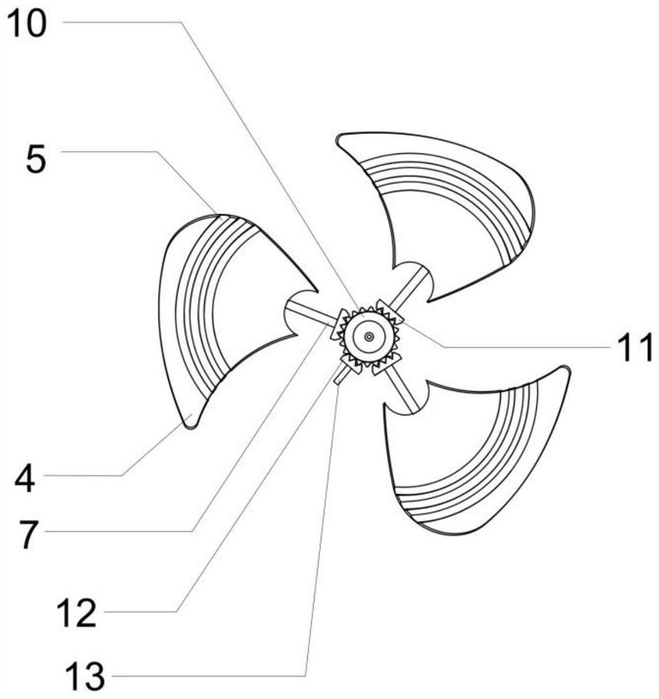
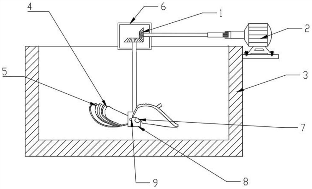
[0033] Such as figure 1 As shown, it is a structural diagram of a fan blade device provided by an embodiment of the present invention, including:

[0034] Central bevel gear 10, at least one side bevel gear 11 meshes with the side of the central bevel gear 10;

[0035] The turbine blade 4 is fixedly connected to the end of the side bevel gear 11 away from the central bevel gear 10 through the connecting shaft 7;

[0036] The driving bevel gear 12 is engaged on...


PUM


Abstract

The invention is suitable for the technical field of corrosion and protection of metal materials, and provides a fan blade device, wave making equipment and a wave making method. The fan blade devicecomprises a center bevel gear, a turbine blade, a driving bevel gear and a rotating shaft, wherein at least one side bevel gear is meshed with a side edge of the center bevel gear; the turbine blade is fixedly connected to the end, which is away from the center bevel gear, of the side bevel gear through a connecting shaft; the driving bevel gear is meshed with the center bevel gear and is used fordriving the center bevel gear to rotate; and the rotating shaft is coaxially and fixedly connected to the end, which is away from the center bevel gear, of the driving bevel gear and is used for applying rotating torsion of the driving bevel gear. According to the fan blade device, the wave making equipment and the wave making method, torsion is applied to the rotating shaft, the rotating shaft drives the driving bevel gear to rotate so as to drive the center bevel gear to rotate, the center bevel gear drives the side bevel gear to rotate so as to enable the connecting shaft to drive the turbine blade to rotate, then the inclination angle of the turbine blade is changed, the height and the amplitude of discharged air and splashed liquid of the turbine blade are controlled, and thus, control of the wind blowing or wave making mode is completed.

Description

technical field [0001] The invention belongs to the technical field of corrosion and protection of metal materials, and in particular relates to a fan blade device, wave-making equipment and a wave-making method. Background technique [0002] In the ocean splash area, the corrosion effect in this area is particularly significant due to seawater splash scour, alternating dry and wet, sun exposure, and full aeration of the surface. The corrosion of the steel structure in the splash irrigation area is very serious, causing great economic losses; It is very important to study the corrosion behavior of this complex alternating wet and dry environment. However, due to the limitation of actual conditions, the corrosion experiments of laboratory simulation of such environments are generally used to calculate the corrosion behavior of metals in this actual environment; due to the complexity of waves in the natural state, it is difficult to Devices and methods are also uneven, so it ...

Claims


Application Information

Patent Timeline
IPC IPC(8): F04D29/18F04D35/00E02B1/02
CPCE02B1/02F04D29/18F04D35/00
Inventor 亢淑梅徐美玲严新永路金林郭菁赵清平
Owner UNIV OF SCI & TECH LIAONING
Why Eureka
Try Eureka