Super-thick material layer distribution method

A thick material layer and cloth technology, which is applied in the field of ultra-thick material layer cloth, can solve the problems such as the inability to meet the requirements of the material layer air permeability, and achieve the effects of good sintered ore quality, increased particle size, and reduced extrusion damage.

Pending Publication Date: 2020-09-22
NANKAI UNIV
View PDF0 Cites 0 Cited by
  • Summary
  • Abstract
  • Description
  • Claims
  • Application Information

AI Technical Summary

Problems solved by technology

[0004] Therefore, the technical problem to be solved in the present invention is to overcome the cloth method in the prior art, when it is used for the ultra-thick material layer cloth that the material layer thickness reaches 1000mm, it cannot meet the defect that the material layer requires air permeability, thereby providing A method for distributing super-thick material layers

Method used


Image

  • Super-thick material layer distribution method
  • Super-thick material layer distribution method
  • Super-thick material layer distribution method

Examples


Embodiment 1

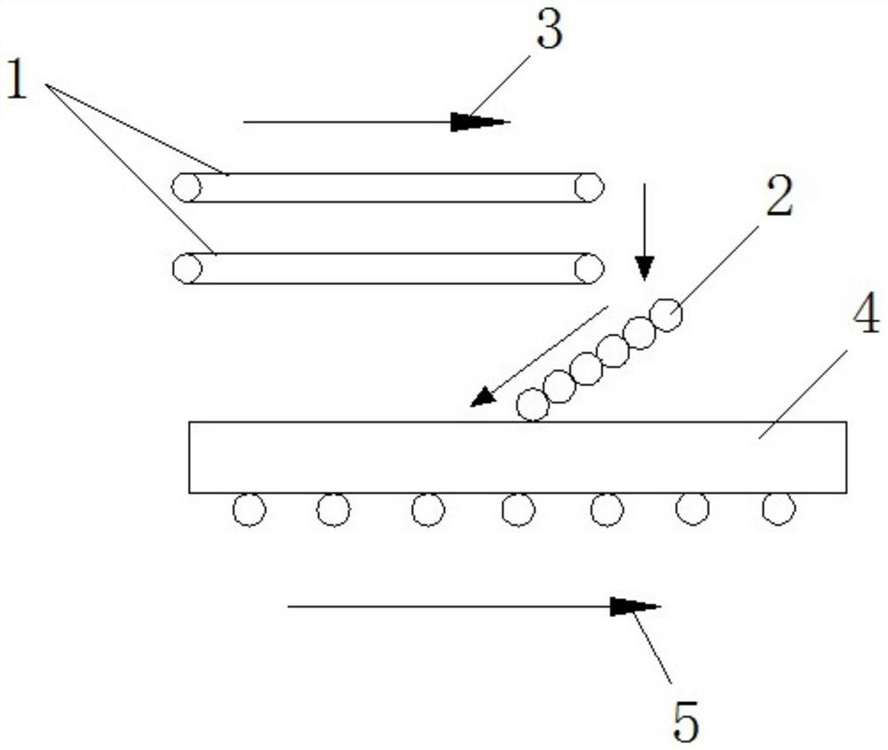
[0036] This embodiment provides a specific implementation of an ultra-thick material layer distributing equipment, such as figure 1 As shown, it includes: conveyor 1 and multi-roller distributor 2. Wherein said feeder 1 has two sets that are arranged in parallel and spaced up and down, and the width of the upper and lower two feeder 1s is 2600mm wide. In addition, as an alternative embodiment, there may be more than two conveyors 1 as required, and the width of the conveyor 1 may be between 2600 mm and 3000 mm.

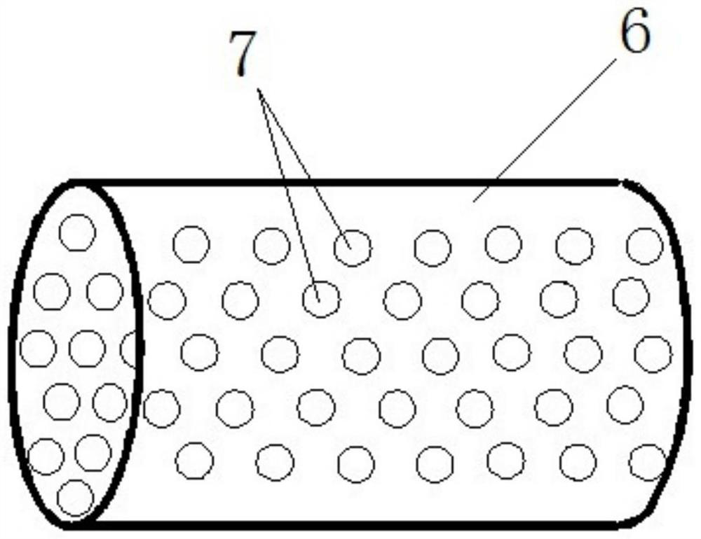
[0037] Such as figure 1 As shown, the multi-roller distributor 2 is received below the outlet of the conveyor 1, the multi-roller distributor 2 is specifically: a six-roller distributor, and the six-roller distributor has six rotatable rollers 6, Each roller 6 has a diameter of 250 mm. In addition, as an alternative embodiment, the multi-roller distributor 2 can also be other multi-roller distributors 2 except the six-roller distributor, and the diameter of each ro...

Embodiment 2

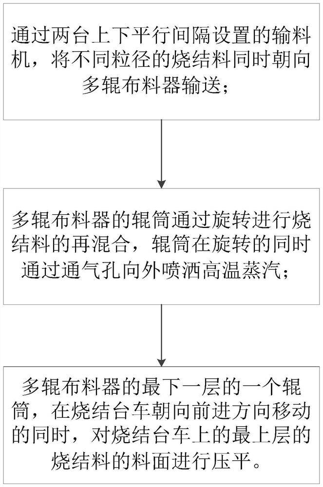
[0042] This embodiment provides a specific implementation of a method for distributing an ultra-thick material layer, and the equipment for distributing an ultra-thick material layer as described in Example 1 can be used, specifically as image 3 shown, including the following steps:

[0043]Step 1: Convey the sintered materials with different particle sizes towards the multi-roller distributor 2 at the same time through two conveyors 1 arranged in parallel and spaced up and down; specifically, the conveyor 1 located above is used to convey the particle size is about 3mm The ore return, the conveyor 1 located below is used to transport the sintered material after secondary mixing, and the returned ore and sintered material fall from the conveyor 1 at the same time, which is conducive to uniform mixing.

[0044] Step 2: During the distributing process, the roller 6 of the multi-roller distributor 2 rotates, and the sintering material is remixed through the rotation of the rolle...


PUM

PropertyMeasurementUnit
widthaaaaaaaaaa

Abstract

The invention provides a super-thick material layer distribution method and belongs to the technical field of metallurgy. The super-thick material layer distribution method comprises the following steps of conveying sintered materials in different grain sizes to the same position of a multi-roller distributor through at least two conveyors; conveying the sintered materials downwards to a sinteringpallet through the multi-roller distributor arranged obliquely; and spraying high-temperature steam from a roller body of at least one roller of the multi-roller distributor to be mixed with the sintered materials while conveying the sintered materials. According to the super-thick material layer distribution method, the sintered materials are conveyed on the multi-roller distributor, and simultaneously, the high-temperature steam sprayed from the roller bodies of the multi-roller distributor is mixed with the sintered materials; through the high-temperature steam, the grain diameter of the sintered materials can be increased, and the grain structure can be enhanced; meanwhile, through the high-temperature steam, the material temperature can be increased, the thickness of an excessive moist layer in a material layer can be reduced, and accordingly, the breathability of a sintered material layer can meet the requirement for sintering of the super-thick material layer.

Description

technical field [0001] The invention relates to the technical field of metallurgy, in particular to a method for distributing super-thick material layers. Background technique [0002] In sintering production, it includes the main processes of distributing, ignition, sintering and so on. The distributing is to distribute the mixture evenly on the sintering trolley through the distributing equipment. When distributing, the particle size and chemical composition of the mixture are required to be uniform along the horizontal and vertical directions of the sintering trolley. Distributed, and has a certain degree of looseness, and the surface is flat. [0003] At present, the conventional distribution of sintering trolleys in my country adopts the process of shuttle distributor + mixing hopper + round roller feeder + multiple distributors (or reflectors). The ultra-thick material layer of 900-1000mm requires more advanced fabric technology to meet the air permeability requirement...

Claims


Application Information

Patent Timeline
Patent Type & Authority Applications(China)
IPC IPC(8): F27B21/08F27B21/10F27D3/12
CPCF27B21/00F27D3/123F27D2003/125
Inventor 于宏兵曹玉鑫于晗王通李英杰
Owner NANKAI UNIV
Why Eureka
Try Eureka