Floating type water level alarm device for hydropower station

A water level alarm, floating technology, applied in measuring devices, buoy liquid level indicators, instruments, etc., can solve the problems of long sampling period, frequent fluctuations in the conduction and disconnection of the alarm device, and reducing the immediacy and accuracy of the alarm device. , to improve the working stability and service life, improve the monitoring stability and service life, and improve the water barrier effect and stability.

Active Publication Date: 2020-09-22
STATE GRID CORP OF CHINA +2
View PDF5 Cites 0 Cited by
  • Summary
  • Abstract
  • Description
  • Claims
  • Application Information

AI Technical Summary

Problems solved by technology

[0004] However, this kind of water level alarm device will cause its terminals to be soaked in water for a long time, causing the water body to form continuous corrosion and erosion on the terminals after soaking, which is prone to malfunction or damage, has low stability and requires regular maintenance. and replace
In addition, when the water level rises and falls, it will cause its water surface to fluctuate up and down. When the water surface is at a critical position with the terminal, the floating state will cause the alarm to frequently fluctuate between conduction and disconnection
In response to this phenomenon, the conventional alarm device only uses the conventional first-order lag filter algorithm to overcome the periodic interference caused by high-frequency fluctuations; however, this filter algorithm has the problems of long sampling period and low sensitivity. , large changes, it is difficult for the system to respond quickly and give an alarm, which reduces the immediacy and accuracy of the alarm device in the monitoring process
[0005] Therefore, the existing water level alarm device for water level monitoring has the problems of poor monitoring stability and easy damage to the alarm

Method used


Image

  • Floating type water level alarm device for hydropower station
  • Floating type water level alarm device for hydropower station
  • Floating type water level alarm device for hydropower station

Examples


Embodiment Construction

[0028] The present invention will be further described below in conjunction with the accompanying drawings and embodiments, but not as a basis for limiting the present invention.

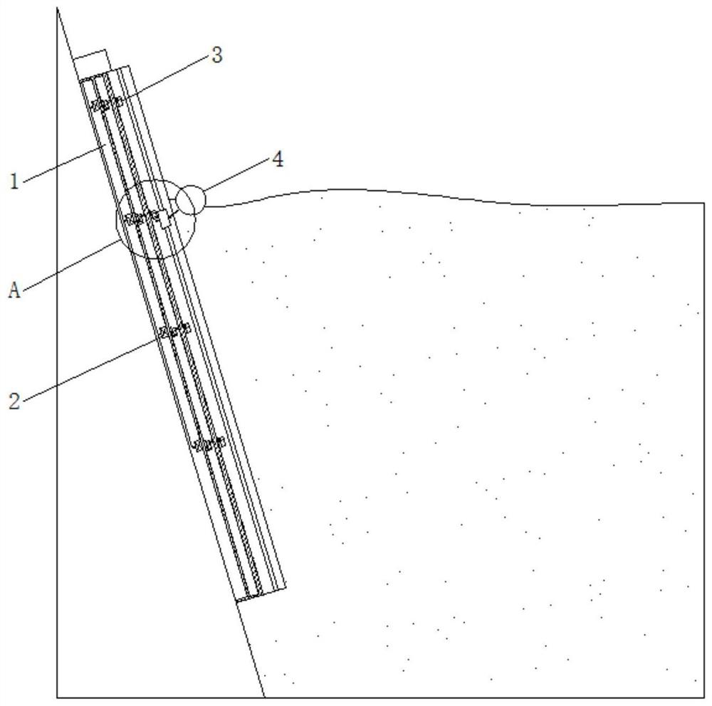
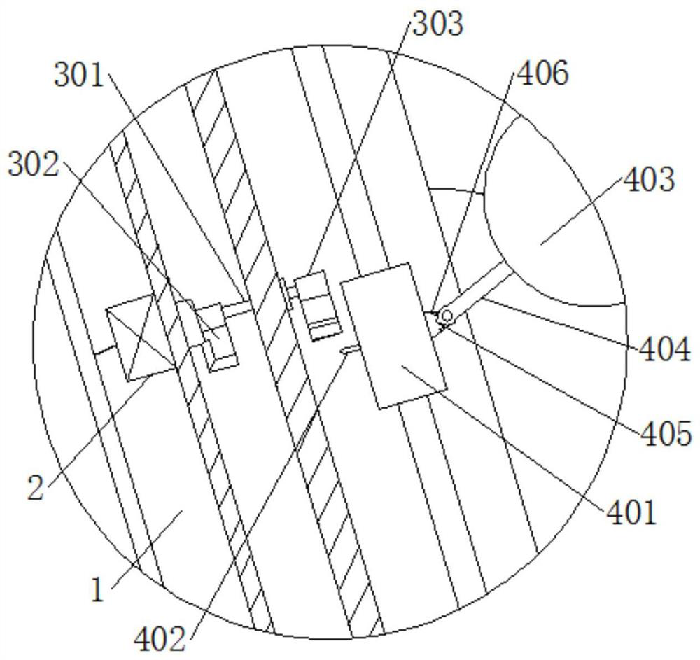
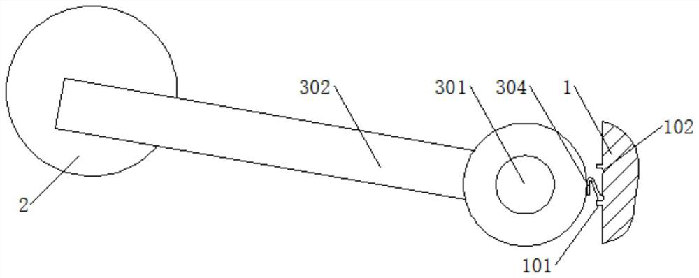
[0029] Example. A floating water level alarm device for a hydropower station, which consists of figure 1 As shown, it includes a measuring frame body 1 fixed on the embankment. The surface of the measuring frame body 1 is provided with a floating assembly 4 that can be lifted. The inside of the measuring frame body 1 forms a sealed chamber. A number of water level alarm switches 2 are distributed at intervals. One side of the water level alarm switch 2 is provided with a swing rod assembly 3 that is rotatably connected to the sealed chamber. One end of the swing rod assembly 3 is in contact with the water level alarm switch 2. The end of the swing rod assembly 3 extends to The outside of the sealed chamber is in contact with the floating component 4 , and the pendulum component 3 and the measuring ...


PUM


Abstract

The invention discloses a floating type water level alarm device for a hydropower station. The device comprises a measuring frame body (1) fixed on a river levee, a liftable floating assembly (4) is arranged on the surface of the measuring frame body (1); a sealed cavity is formed in the measuring frame body (1); a plurality of water level alarm switches (2) are distributed in the sealed cavity atintervals; a swing rod assembly (3) rotationally connected with the sealed cavity is arranged at one side of the water level alarm switch (2), one end of the swing rod assembly (3) makes contact withthe water level alarm switch (2), the end of the swing rod assembly (3) extends to the outer side of the sealed cavity and makes contact with the floating assembly (4), and the swing rod assembly (3)and the measuring frame body (1) are connected through a sealing assembly (5). The device has the characteristics that the monitoring stability is high, and the alarm is not easy to damage.

Description

technical field [0001] The invention relates to a water level alarm device, in particular to a floating water level alarm device for a hydropower station. Background technique [0002] The water level difference between the upstream diversion section of the hydropower station and the downstream tailrace section is an important parameter for the hydropower station to adjust the operation of the turbine. When the water level is too high or the flood peak comes, if there is no stable water level monitoring system for early warning, it will cause damage to the dam. serious safety issue. Since the water body monitored by the hydropower station has the characteristics of large depth and complex operating environment, its sensors are easily affected by heavy rain, floods or fast-flowing water flow, which seriously reduces its monitoring accuracy; and as the operating time increases, the accuracy and stability of the sensor The performance and detection accuracy are also reduced. ...

Claims


Application Information

Patent Timeline
Patent Type & Authority Applications(China)
IPC IPC(8): G01F23/70
CPCG01F23/703
Inventor 马明刚严良平黄彦庆王建忠郑贤喜程剑林晁新刚徐步超吴刚周智叶宇杰汪伟铤
Owner STATE GRID CORP OF CHINA
Why Eureka
Try Eureka