
Digital pulse signal width measurement circuit and measuring method

A technology of signal width and digital pulse, which is applied in the field of digital pulse signal width measurement circuit, can solve the problems of limiting the working range of the sampling clock and increasing the cost of software and hardware, and achieves the effect of simple structure, wide application range and low resource cost

Active Publication Date: 2020-09-22
HUNAN GREAT LEO MICROELECTRONICS CO LTD
View PDF19 Cites 16 Cited by
  • Summary
  • Abstract
  • Description
  • Claims
  • Application Information

AI Technical Summary

Problems solved by technology

However, this method limits the operating range of the sampling clock. At the same time, it requires a separate capture delay chain and periodically executes the software calibration procedure, which increases the hardware and software overhead.

Method used


Image

  • Digital pulse signal width measurement circuit and measuring method
  • Digital pulse signal width measurement circuit and measuring method
  • Digital pulse signal width measurement circuit and measuring method

Examples


Embodiment Construction

[0045] The present invention will be further described in detail below in conjunction with the accompanying drawings and specific embodiments.

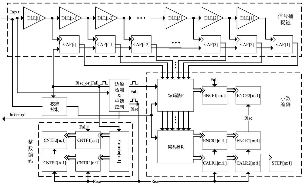
[0046] Such as figure 2 Shown is a structural principle diagram of the ultra-high precision digital pulse signal width measuring circuit in a specific application example of the present invention. For simplicity, in figure 2 The sampling clock and its connection relationship with other circuits are not shown in the figure, but this does not hinder the understanding of the technical solution of the present invention by ordinary persons in the art, nor does it affect the actual protection scope of the present invention.

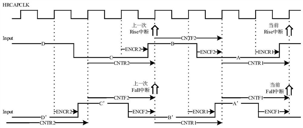
[0047] The ultra-high-precision digital pulse signal width measurement circuit of the present invention includes an edge detection and interruption control unit, an integer encoding unit, a signal capture chain, a decimal encoding unit, a calibration control unit, and a sampling clock HRCAPCLK; wherein:

[0048] Th...


PUM


Abstract

The invention discloses a digital pulse signal width measurement circuit and method, and the measurement circuit comprises a sampling clock which is used for driving all registers in a circuit; an edge detection and interruption control unit, used for detecting a rising edge and a falling edge of a pulse signal on the input pin Input so as to control signal acquisition; an integer encoding unit, comprising a counter and a register and used for measuring an integer part mu of the width of a high level or a low level on the input pin Input by taking 1 / f of one period of the sampling clock as a reference unit; a signal capture chain, used for sampling an output level value of each delay unit DLL; a decimal encoding unit, used for finding out and recording the propagation position of the pulseedge on the signal capture chain; and a calibration control unit, used for calibration. The measurement method is realized based on the measuring circuit. The method has the advantages of high precision, simple structure, low resource cost and the like.

Description

technical field [0001] The invention mainly relates to the technical field of high-precision digital pulse signal measurement, in particular to a digital pulse signal width measurement circuit and a measurement method. Background technique [0002] In a large number of industrial and consumer equipment and instruments, it is generally necessary to measure voltage, current, capacitance, speed, distance and other signals, and the measurement accuracy directly affects the accuracy of equipment and instruments. [0003] High-precision digital pulse signal width measurement is widely used in pulse sequence period / duty cycle measurement, instantaneous speed measurement, voltage measurement across isolation boundaries, distance / sonar measurement and scanning, capacitive touch sensing and other applications. [0004] In digital signal processing devices, the signal measurement is generally to quantify the voltage, capacitance, speed, distance and other signals into digital pulse ...

Claims


Application Information

Patent Timeline
Patent Type & Authority Applications(China)
IPC IPC(8): G01R29/02
CPCG01R29/023
Inventor 陈虎许野万江华
Owner HUNAN GREAT LEO MICROELECTRONICS CO LTD
Learn More