A direction finding method and system based on a radio frequency analog receiving system

A receiving system and radio frequency technology, which is applied to direction finders using radio waves, direction finder, radio wave measurement systems, etc. Advanced problems, to avoid unbalanced input signal amplitude, avoid logic judgment and other operations, and improve the effect of direction finding accuracy

Active Publication Date: 2022-08-09
SOUTHWEST CHINA RES INST OF ELECTRONICS EQUIP
View PDF7 Cites 0 Cited by
  • Summary
  • Abstract
  • Description
  • Claims
  • Application Information

AI Technical Summary

Problems solved by technology

[0011] (c) Insufficient application of the antenna leads to low accuracy;
[0012] (d) Unbalanced signal strength input to the phase detector

Method used


Image

  • A direction finding method and system based on a radio frequency analog receiving system
  • A direction finding method and system based on a radio frequency analog receiving system
  • A direction finding method and system based on a radio frequency analog receiving system

Examples


Embodiment Construction

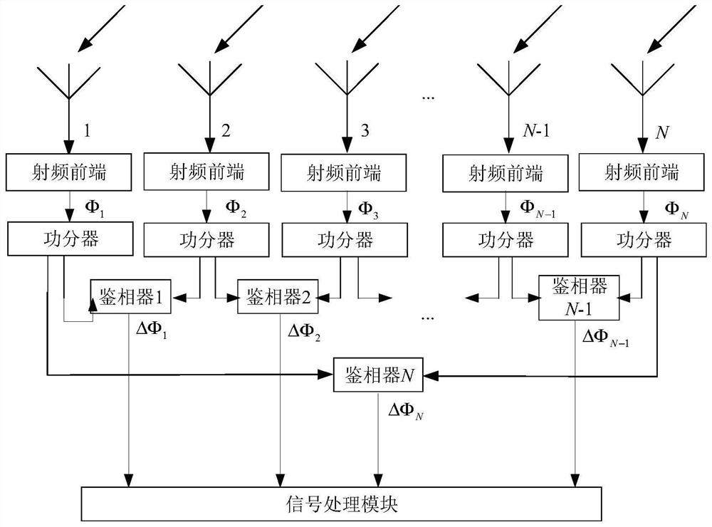
[0059] The present invention will be further described below with reference to the accompanying drawings.

[0060] The present invention provides a two-dimensional incident angle measurement method with simple implementation and high precision. figure 1 The radio frequency analog receiving system shown, its main function is to convert space electromagnetic waves into phase differences. After the antenna receives the signal, it is amplified and filtered by the RF front-end, and then enters the one-to-two power divider. After splitting, two-two phase detection is used. The second antenna and the first antenna are phase-detected, and the phase difference is ΔΦ. 1 ; Phase detection between the third antenna and the second antenna, and the phase difference is recorded as ΔΦ 2 ; And so on to the Nth antenna and the N-1th antenna phase detection, record the phase difference as ΔΦ N-1 . The first antenna and the Nth antenna are phase-detected, and the phase difference is recorded a...


PUM


Abstract

The invention provides a direction finding method based on a radio frequency analog receiving system. For an N-element uniform circular array antenna, the phase difference between each antenna and adjacent antennas is obtained through a phase detector, and recorded as the phase of the phase detector. difference; when the incoming wave is incident on the circular array antenna with the elevation angle of 0°, the phase difference of each phase detector is recorded as the initial phase difference; the complex number corresponding to each phase detector is constructed; according to the elevation angle and azimuth angle, k is the number of iterations , calculate the theoretical phase difference of each phase detector; introduce the vector X and the direction vector G, and combine the constructed complex numbers to calculate the elevation angle and azimuth angle of the two-dimensional incident angle with the iteration number k+1; the calculation iteration number is k+1 and the iteration The difference between the two-dimensional incident angles of order k is compared with the threshold value, and if it is less than the threshold value, it enters the output elevation and azimuth angles; otherwise, the value of k is increased by 1, and the theoretical phase difference is calculated. The advantage of the method lies in that it avoids the problems of operations such as logical judgment, phase ambiguity, and unbalanced amplitude of the input signal of the phase detector, and improves the direction finding accuracy.

Description

technical field [0001] The invention relates to the technical field of radio monitoring, in particular to a direction finding method and system based on a radio frequency analog receiving system. Background technique [0002] The interferometer direction finding system belongs to the phase direction finding system. When the incoming wave arrives at the direction finding antenna array, the different spatial positions of the different antennas lead to different phases of the signals received by each antenna unit to obtain the direction information of the incoming wave. Interferometer direction finding technology has been widely used in the field of passive direction finding because of its high precision, clear principle and wide frequency band. [0003] Due to its high direction finding accuracy, phase interferometer is a direction finding method commonly used in current direction finding systems. Because of the simple operation of the linear least squares method, the phase i...

Claims


Application Information

Patent Timeline
Patent Type & Authority Patents(China)
IPC IPC(8): G01S3/48G01S3/04
CPCG01S3/48G01S3/043
Inventor 左乐聂剑坤应钱诚张浩斌唐勇王秀君胡泽华范保华
Owner SOUTHWEST CHINA RES INST OF ELECTRONICS EQUIP
Why Eureka
Try Eureka