
Lamp optical design method and system based on solid-state light source

A technology of optical design and solid-state light source, applied in design optimization/simulation, computing, lighting and heating equipment, etc., can solve the problems of inaccurate design, poor portability, and poor applicability of optical devices, and achieve The effect of fast and efficient design, reducing time and cost

Pending Publication Date: 2020-09-22
节律照明科技(中山)有限公司
View PDF4 Cites 0 Cited by
  • Summary
  • Abstract
  • Description
  • Claims
  • Application Information

AI Technical Summary

Problems solved by technology

At present, the main shortcomings of lighting optical design are as follows: 1. The applicability of optical devices designed for specific light sources and specific lighting targets is not strong; 2. The traditional optical design method is to treat the light source as a point light source. , For example, in terms of new solid-state light sources such as LED and OLED, precise design cannot be achieved; 3. A specific optical system or optical device must be designed for each lamp, and the portability is not strong

Method used

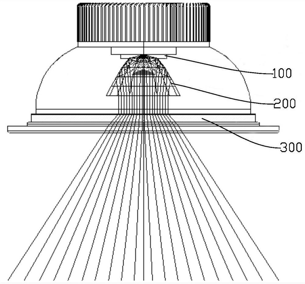

Image

  • Lamp optical design method and system based on solid-state light source
  • Lamp optical design method and system based on solid-state light source
  • Lamp optical design method and system based on solid-state light source

Examples


Embodiment Construction

[0024] Embodiments of the present invention are described in detail below, examples of which are shown in the drawings, wherein the same or similar reference numerals designate the same or similar elements or elements having the same or similar functions throughout. The embodiments described below by referring to the figures are exemplary only for explaining the present invention and should not be construed as limiting the present invention.

[0025] In the description of the present invention, it should be understood that the orientation descriptions, such as up, down, front, back, left, right, etc. indicated orientations or positional relationships are based on the orientations or positional relationships shown in the drawings, and are only In order to facilitate the description of the present invention and simplify the description, it does not indicate or imply that the device or element referred to must have a specific orientation, be constructed and operated in a specific ...


PUM


Abstract

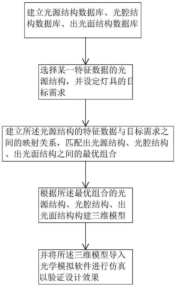
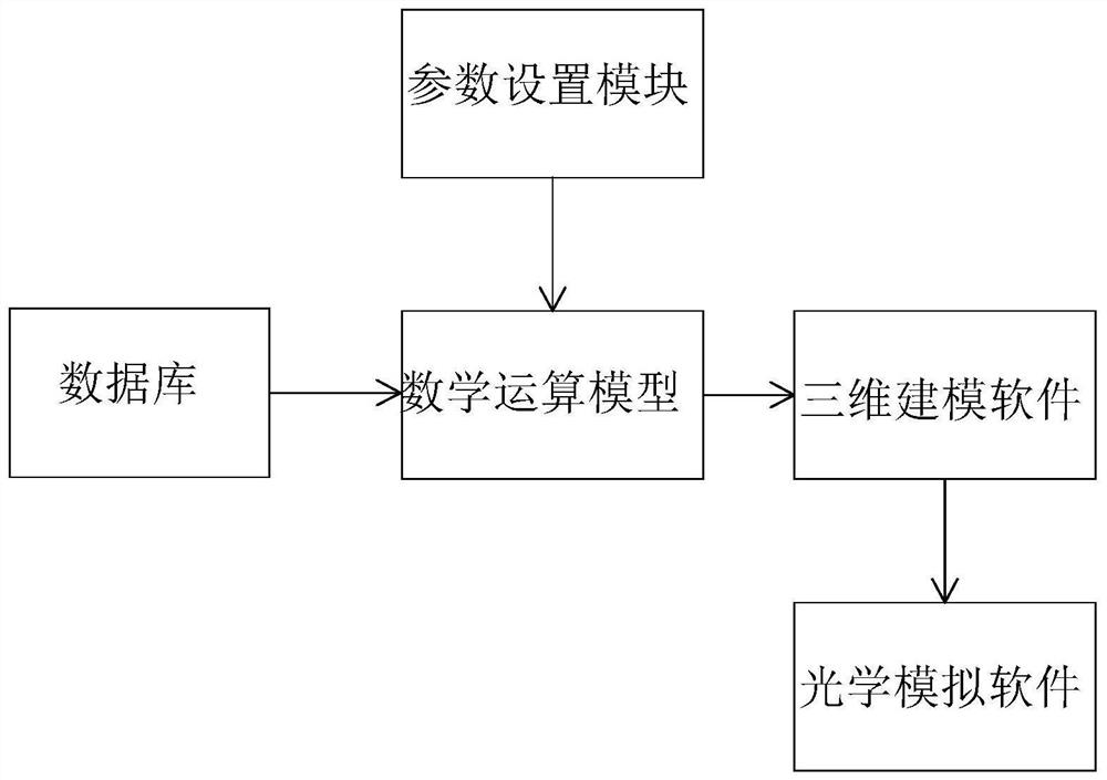
The invention discloses a lamp optical design method and system based on a solid-state light source. The lamp optical design method comprises the steps: establishing a light source structure database,an optical cavity structure database and a light emitting surface structure database; selecting a light source structure of a certain characteristic data from the light source structure database, andsetting a target demand of the lamp; and establishing a mapping relationship between the feature data of the light source structure and a target demand, automatically adding the light cavity structure and the light emitting surface structure from the light cavity structure database and the light emitting surface structure database according to the mapping relationship, and matching an optimal combination among the light source structure, the light cavity structure and the light emitting surface structure. By constructing the lamp design model and the corresponding database, the optimal combination scheme among the light source structure, the light cavity structure and the light emitting surface structure can be quickly and efficiently designed only by providing set lamp target requirements by a user, so that the time and the cost of a design link are reduced.

Description

technical field [0001] The invention relates to the field of lighting lamps, in particular to an optical design method and system for lamps based on solid-state light sources. Background technique [0002] Non-imaging optics is a new branch of geometric optics. It has risen rapidly with the development of LED and other new solid-state light source lighting technologies. It is a new discipline for the study of light energy transmission and control. At present, the main shortcomings of lighting optical design are as follows: 1. The applicability of optical devices designed for specific light sources and specific lighting targets is not strong; 2. The traditional optical design method is to treat the light source as a point light source. , For example, in terms of new solid-state light sources such as LEDs and OLEDs, precise design cannot be achieved; 3. A specific optical system or optical device must be designed for each lamp, and the portability is not strong. Contents of ...

Claims


Application Information

Patent Timeline
Patent Type & Authority Applications(China)
IPC IPC(8): G06F30/10G06F30/20G06T17/00F21V5/00F21V5/04F21V7/00G06F111/06
CPCG06F30/10G06F30/20G06T17/00F21V5/00F21V5/04F21V7/00G06F2111/06
Inventor 吕佳川夏雨
Owner 节律照明科技(中山)有限公司
Learn More