Method for wire-cutting controlling metal wire moving

A technology of metal wire and wire cutting, which is applied in the direction of metal processing equipment, electrode manufacturing, accessory devices, etc., and can solve the problems of unstable tension and acceleration of metal wire a

Inactive Publication Date: 2003-08-06
TAKATORI
View PDF0 Cites 2 Cited by
  • Summary
  • Abstract
  • Description
  • Claims
  • Application Information

AI Technical Summary

Problems solved by technology

[0009] d, if the multi-groove roller 5 and the pulley 12, 13 or between the supply wheel and the take-up wheel are out of sync, the su

Method used


Image

  • Method for wire-cutting controlling metal wire moving
  • Method for wire-cutting controlling metal wire moving
  • Method for wire-cutting controlling metal wire moving

Examples


Embodiment Construction

[0030] Embodiments of the present invention combine figure 1 Make an explanation.

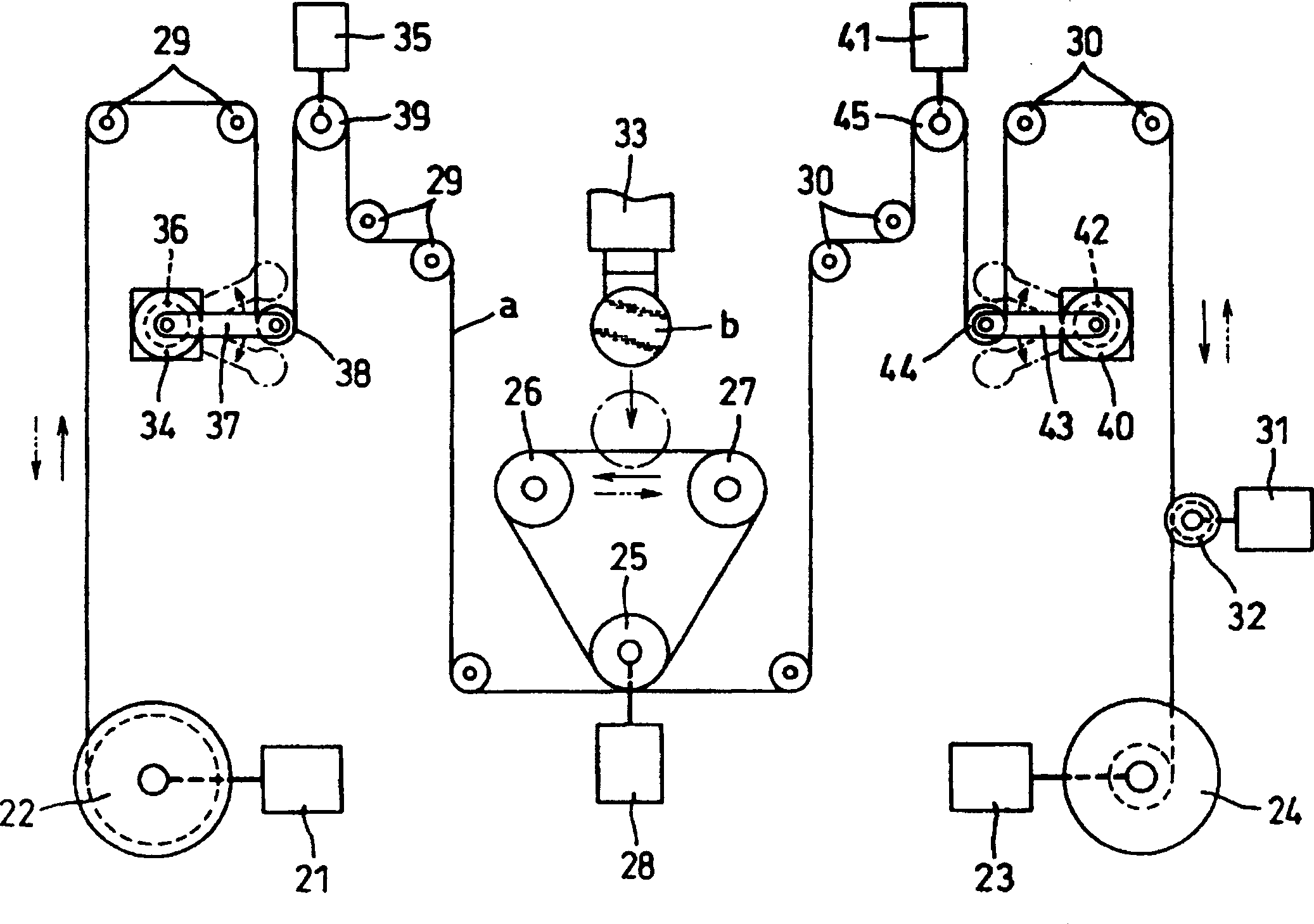
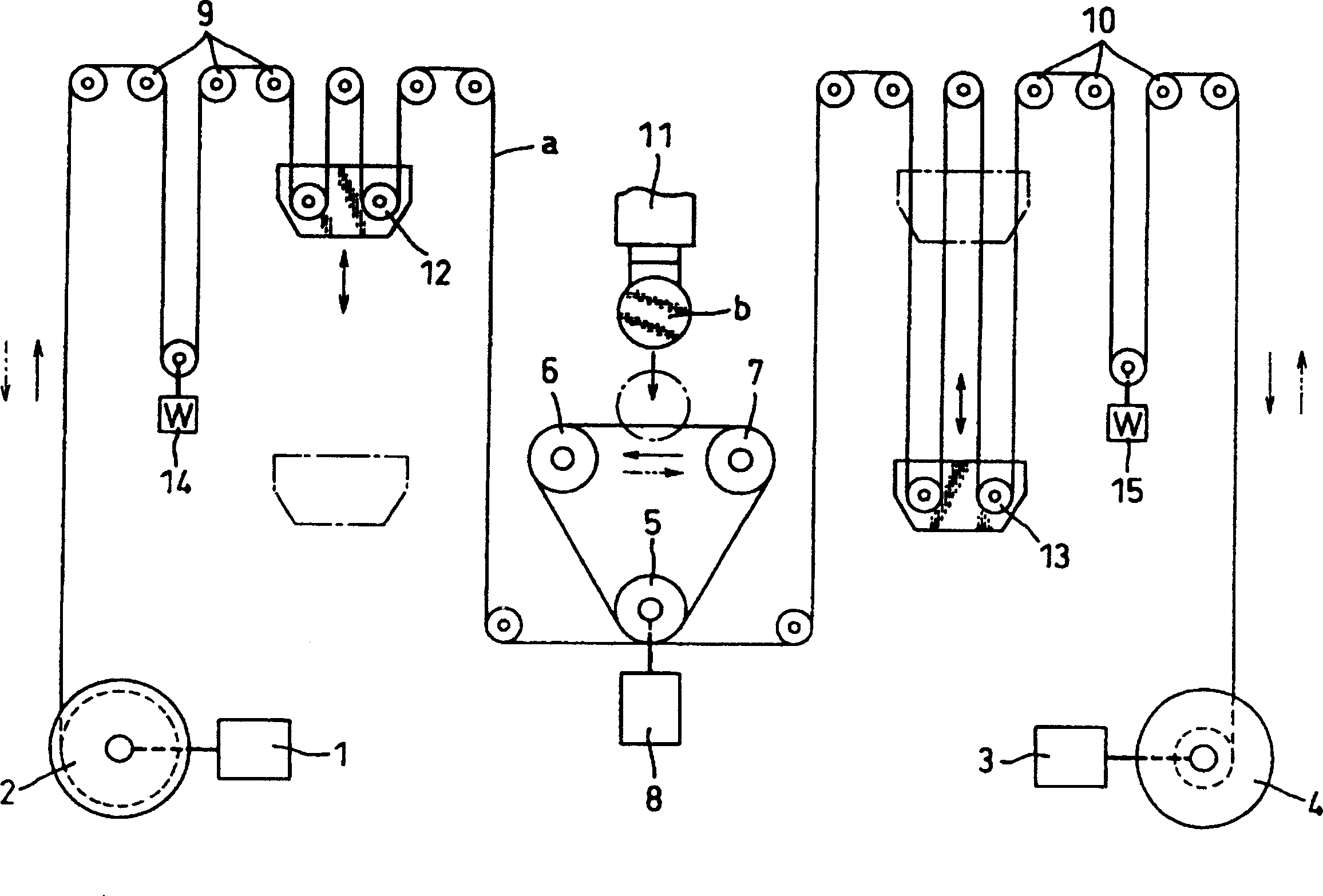
[0031] figure 1 It is an embodiment of the wire cutting method using the present invention to control the running of the metal wire. Between the wire feeding reel 22 that feeds and takes up the metal wire a through the forward and reverse rotation of the power motor 21 and the wire take-up reel 24 that also performs the wire take-up and wire feeding through the forward and reverse rotation of the power motor 23 Between, three multi-groove rollers 25, 26, 27 are installed, wherein one multi-groove roller 25 is driven by the power motor 28 to carry out forward and reverse rotation, while the metal wire a drawn from the wire supply wheel 22 passes through a plurality of guide wheels 29, Lead to the multi-groove rollers 25, 26, 27, after the outer circumference of the multi-groove rollers 25, 26, 27 is repeatedly wound side by side, then through a plurality of guide wheels 30 and the longitudin...


PUM


Abstract

The present invention relates to a wire traveling control method. A wire is wrapped on the multislot roller between a supply roller and a recovery roller, at start of operation, the three rollers are normally rotated and a wire is traveled at a low speed. A correlative speed ratio is calculated at a time when traveling of the wire is stabilized. The respective driving motors are simultaneously started at a high speed on the basis of the speed ratio. Next, the speed ratio of the supply roller driving motor and the recovery roller driving motor with respect to the multislot roller driving motor at the high speed traveling is stored. The respective driving motors are controlled to reversely rotate with the stored speed ratio at returning traveling of the wire, which is repeated at reciprocating traveling of the wire thereafter, thereby to realize the control to a metal wire. The structure of the application device of the present invention is simple and wire additional tension is steady.

Description

technical field [0001] The invention relates to a control method for making the metal wire run under the optimal tension condition in the wire cutting which uses the metal wire to reciprocate at high speed and cuts the workpiece with the arranged metal wire. Background technique [0002] image 3 A wire cutting method for controlling the running of a metal wire using the prior art is shown. The wire feeding reel 2 is driven by the forward or reverse rotation of the motor 1 to feed and take up the metal wire, and the same is driven by the forward or reverse rotation of the motor 3. The take-up reel 4 is used to feed and take up the metal wire. Three multi-groove rollers 5, 6, 7 are installed between the wire supply reel 2 and the take-up reel 4, wherein when the multi-groove roller 5 is driven by the motor 8 to perform forward and reverse rotation, the metal drawn from the wire supply reel 2 The wire is led to the multi-groove rollers 5, 6, 7 after passing through a pluralit...

Claims


Application Information

Patent Timeline
IPC IPC(8): B24B27/06B23H7/10B23H7/26B23H11/00B65H59/38
Inventor 米田龙也
Owner TAKATORI
Why Eureka
Try Eureka