
DC power transmission system locking method for multi-VSC parallel structure

A DC transmission system and paralleling technology, applied in electrical components, power transmission AC networks, emergency protection circuit devices, etc., can solve problems affecting the converter valve, the operating life of the arrester, the excess energy of the parallel arrester in the blocking sequence, and equipment damage, etc. Achieve the effect of reducing manufacturing cost, reducing overvoltage and reducing damage

Active Publication Date: 2020-09-22
NR ELECTRIC CO LTD +1
View PDF2 Cites 0 Cited by
  • Summary
  • Abstract
  • Description
  • Claims
  • Application Information

AI Technical Summary

Problems solved by technology

[0003] In a multi-VSC parallel structure, when a ground fault occurs in a VSC converter, the relevant protection action can quickly block the faulty VSC converter, but due to the existence of anti-parallel diodes, the current of the non-faulty VSC converter will still flow into the faulty VSC converter. point, causing sustained damage to the device
In addition, for faults in the valve side area of ​​the VSC converter, improper blocking sequence design can easily cause overvoltage of the VSC converter sub-modules in the parallel group and excess energy of the parallel arrester, seriously affecting primary equipment such as converter valves and arresters. operating life of
Aiming at the above problems, a multi-VSC parallel structure DC transmission system blocking method is proposed to solve the overvoltage problem of blocking when the valve side of the VSC converter is faulty, and to quickly block the fault outside the valve side of the VSC converter. sexual problems

Method used

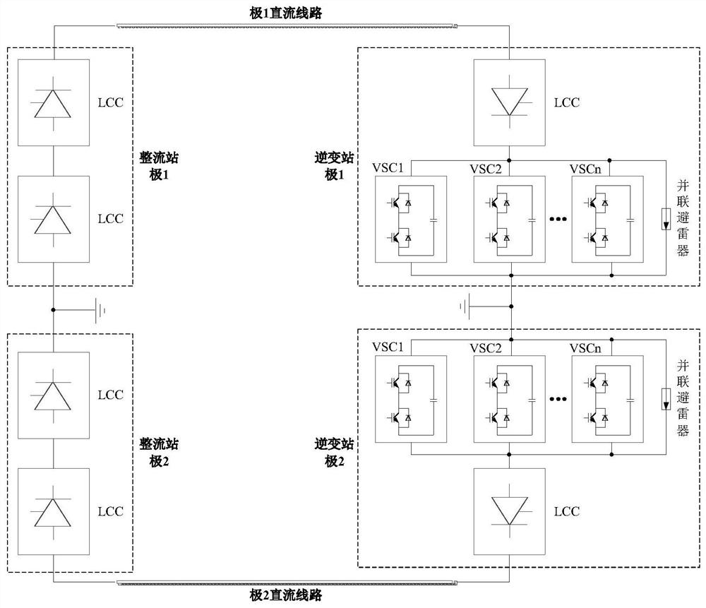
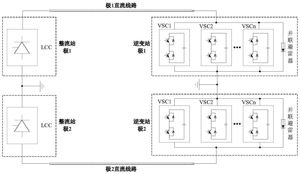
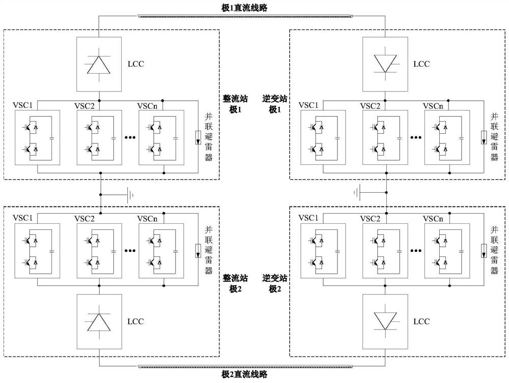

Image

  • DC power transmission system locking method for multi-VSC parallel structure
  • DC power transmission system locking method for multi-VSC parallel structure
  • DC power transmission system locking method for multi-VSC parallel structure

Examples


Embodiment 1

[0029] Example 1: When a ground fault occurs at point F1, the valve side connection line differential protection and bridge arm current unbalance protection in Type I protection operate, the VSC differential protection in Type II protection and the 400kV differential protection in Type III protection Protection and extreme differential protection may also operate, but the action time is later than type I protection. After the type I protection operates, immediately block the VSC1 converter and trip the AC switch, and at the same time issue a blocking command to the opposite station immediately, the high-end LCC converter of this station immediately executes blocking and jumps the AC switch, and the station T1 (taking 100ms ) for Type II and Type III protections that appear in the inner shield, the non-faulty VSC2~VSCn converters of the local station perform blocking and jump the AC switch after a delay of T2 (take 100ms), and immediately after the opposite station receives the ...

Embodiment 2

[0031] Example 2: When a ground fault occurs at point F4, the VSC DC link differential protection and VSC differential protection in Type II protection will operate, and the 400kV differential protection and pole differential protection in Type III protection may also operate, but the The time is later than type II protection. After type II protection action: method 1, immediately block the VSC1 converter and trip the AC switch, and immediately issue a blocking command to the opposite station, the LCC converter of this station immediately executes blocking and jumps the AC switch, and the station is not faulty VSC2~ The VSCn converter immediately executes blocking and jumps the AC switch, and immediately executes the whole-pole phase-shift blocking after receiving the blocking command; the second method immediately blocks the VSC1 converter and jumps the AC switch, and waits until the type III protection action, Immediately issue a blocking command to the opposite station, the...

Embodiment 3

[0033] Example 3: When a ground fault occurs at point F6, the 400kV differential protection and extremely differential protection in Type III protection operate. After the type III protection action, immediately block the VSC1 converter and trip the AC switch, and at the same time send a blocking command to the opposite station immediately, the high-end LCC converter of this station immediately executes blocking and trips the AC switch, and the station is not faulty VSC2~VSCn The converter immediately executes the blocking and jumps the AC switch, and the opposite station immediately executes the whole pole phase-shifting blocking after receiving the blocking command.


PUM


Abstract

The invention discloses a DC power transmission system locking method for a multi-VSC parallel structure, and the method comprises the steps: taking measurement points IDCP and IDCN of a current converter DC side sleeve CT as boundaries, and dividing a VSC current converter region into a VSC current converter transformer valve side region inner part and a VSC current converter transformer valve side region outer part; configuring I-type protection, II-type protection and III-type protection for protection in a VSC converter transformer valve side area, protection outside the VSC converter transformer valve side area and protection when faults occur in the whole VSC converter area respectively; during I-type protection action, enabling a fault converter to be immediately locked and trippingan AC switch, and enabling the non-fault converter to execute a delay locking strategy; when only II-type protection and III-type protection act, enabling the fault converter to be immediately lockedand tripping the AC switch, and enabling the non-fault converter to execute a sequential locking strategy. According to the method, the problems of overvoltage of locking during faults in the VSC converter transformer valve side area and rapidity of fault locking outside the VSC converter transformer valve side area are solved, the damage to equipment can be effectively reduced, the manufacturingcost of primary equipment such as a VSC valve and a lightning arrester is reduced, and the service life of the equipment is prolonged.

Description

technical field [0001] The invention relates to a blocking method of a DC power transmission system with a multi-VSC parallel structure, belonging to the technical field of DC power transmission. Background technique [0002] Thyristor-based LCC (Line Commutated Converter) conventional DC transmission systems are widely used because of their large transmission capacity and simple control. However, the inevitable commutation failure in principle often leads to a sudden drop in system power, causing AC voltage and frequency fluctuations. Large oscillations affect the safe operation of the power grid. The commutation of the IGBT-based VSC (Voltage Source Converter) flexible DC transmission system does not depend on the grid voltage, which can effectively avoid the occurrence of commutation failures. There is still a certain gap compared with the device. In order to be applied in high-voltage, long-distance power transmission systems, a parallel structure of multiple VSC conve...

Claims


Application Information

Patent Timeline
Patent Type & Authority Applications(China)
IPC IPC(8): H02H7/26H02J3/36
CPCH02H7/268H02J3/36Y02E60/60
Inventor 唐俊赵文强侍乔明王永平卢宇邹强王冰倩常昊添田杰
Owner NR ELECTRIC CO LTD
Learn More