
Signal transmission method, device and medium of high-speed differential signal line of circuit board

A high-speed differential and signal transmission technology, applied in the directions of printed circuit wiring diagram, printed circuit, printed circuit manufacturing, etc., can solve the problems of affecting signal transmission efficiency, increasing the cost of circuit board manufacturing, and signal distortion at the receiving end, to improve the signal The effect of transmission quality

Active Publication Date: 2021-10-15
GUANGDONG INSPUR BIG DATA RES CO LTD
View PDF0 Cites 0 Cited by
  • Summary
  • Abstract
  • Description
  • Claims
  • Application Information

AI Technical Summary

Problems solved by technology

[0005] However, the plan of using flat cloth and two prepregs will undoubtedly increase the cost of the circuit board, and the offset angle of the wiring will greatly reduce the utilization rate of the board, which also increases the production cost of the circuit board
Although the related technology will improve the calculation accuracy of the transmission rate compared with the traditional technology, and try to make the dielectric constants felt by the two transmission lines of the differential signal the same, but because the final use is still the equivalent dielectric constant provided by the board factory, different areas The dielectric constant will still affect the signal transmission efficiency, causing the signal at the receiving end to be distorted, and will increase the manufacturing cost of the circuit board

Method used


Image

  • Signal transmission method, device and medium of high-speed differential signal line of circuit board
  • Signal transmission method, device and medium of high-speed differential signal line of circuit board
  • Signal transmission method, device and medium of high-speed differential signal line of circuit board

Examples


Embodiment Construction

[0056] In order to enable those skilled in the art to better understand the solution of the present invention, the present invention will be further described in detail below in conjunction with the accompanying drawings and specific embodiments. Apparently, the described embodiments are only some of the embodiments of the present invention, but not all of them. Based on the embodiments of the present invention, all other embodiments obtained by persons of ordinary skill in the art without making creative efforts belong to the protection scope of the present invention.

[0057] The terms "first", "second", "third" and "fourth" in the specification and claims of this application and the above drawings are used to distinguish different objects, rather than to describe a specific order . Furthermore, the terms "comprising" and "having", and any variations thereof, are intended to cover a non-exclusive inclusion. For example, a process, method, system, product, or device compris...


PUM


Abstract

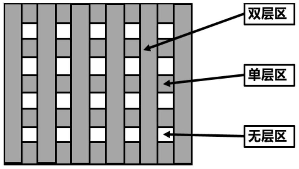
The application discloses a signal transmission method, device and computer-readable storage medium of a high-speed differential signal line of a circuit board. Among them, the method includes calculating the dielectric constant of the glass fiber strip and the gel prepreg according to the equivalent dielectric constant of each type of plate, the proportion of glass fiber cloth and the proportion of resin, and is used to determine whether to cover the glass fiber strip Distinguish the dielectric constant of the first area and the second area; automatically generate the transmission rate information of each signal transmission line in the high-speed differential signal line according to the glass fiber cloth density of the current model plate, the dielectric constant of the first area and the second area , determining the wiring path of the high-speed differential signal line according to the transmission rate information, so as to perform high-speed signal transmission based on the wiring path. On the basis of not increasing the manufacturing cost of the circuit board, it can effectively solve the impact of glass fiber effect on high-speed differential signal transmission, and ensure that the signal received by the receiving end does not have distortion caused by different signals arriving at the same time.

Description

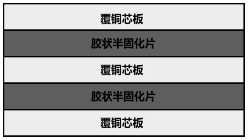
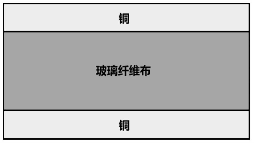
technical field [0001] The present application relates to the technical field of circuit board design of a server, in particular to a signal transmission method, device and computer-readable storage medium of a high-speed differential signal line of a circuit board. Background technique [0002] With the continuous development of the Internet industry, the signal transmission rate continues to increase, and the time of rising edge / falling edge is getting shorter and shorter, which is a severe challenge for the server R&D team. The research and development of the server is inseparable from the circuit board, such as figure 1 Shown is the structure of the circuit pack inside the server. The circuit board is generally composed of multiple layers of copper-clad core boards, and each layer of copper core boards is bonded with a glue-like prepreg. [0003] Such as figure 2 The structure of each copper clad core board is shown, including the first copper clad layer on the upper...

Claims


Application Information

Patent Timeline
Patent Type & Authority Patents(China)
IPC IPC(8): H05K3/00G06F30/3953
CPCG06F30/3953H05K3/0002H05K3/0005
Inventor 马骏驰余华国
Owner GUANGDONG INSPUR BIG DATA RES CO LTD
Learn More