Rapid drainage device for intensive care medicine department
A medical and critical technology, applied in suction equipment, extraction and pumping systems, etc., can solve the problems of affecting cleaning efficiency, insufficient environmental protection, waste of used components, etc., and achieve a highly selective effect.
- Summary
- Abstract
- Description
- Claims
- Application Information
AI Technical Summary
Problems solved by technology
Method used
Image

Examples
Embodiment 1
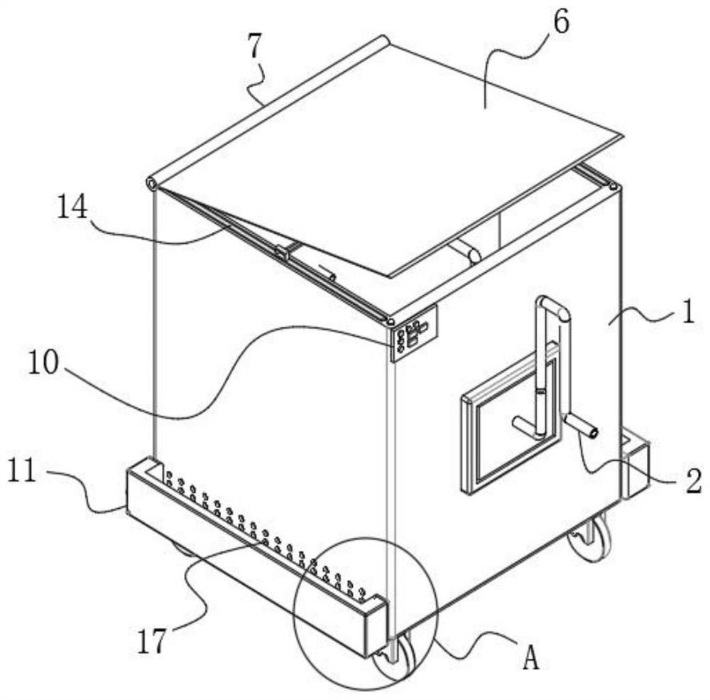
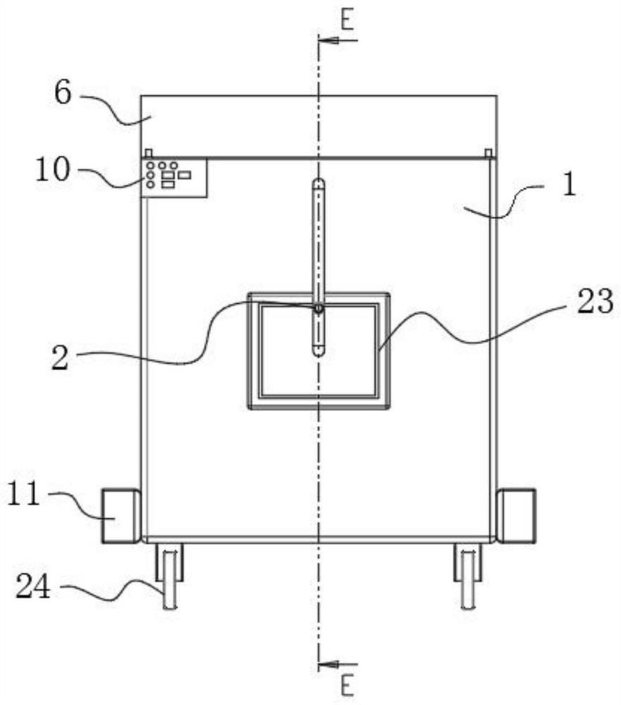
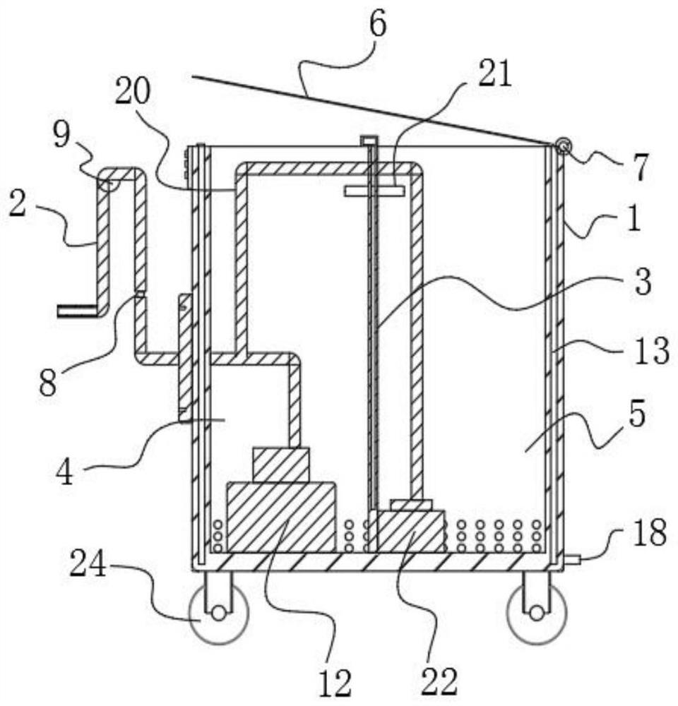
[0030] Please refer to Figure 1-8 Shown: a rapid drainage device for intensive care medicine, including a cabinet body 1 and a drainage tube 2, one end of the drainage tube 2 is connected to the cabinet body 1, and a sewage collection tank 4 and a water storage tank 5 are respectively arranged in the cabinet body 1, and the sewage collection tank A partition plate 3 is connected between the tank 4 and the water storage tank 5. A negative pressure pump 12 is installed inside the dirt collection tank 4. The output end of the drainage pipe 2 is connected to the negative pressure pump 12. Pressure drainage operation, a booster pump 22 is installed inside the water storage tank 5, and a diversion tube 20 is also arranged inside the water storage tank 5, the input end of the diversion tube 20 is connected with the booster pump 22, and the output end of the diversion tube 20 runs through the branch. The separator 3, the output end of the diversion tube 20 is connected to the drain t...
Embodiment 2
[0033] Please refer to Figure 1-8 As shown: an AC pipe 21 is also connected between the dirt collection tank 4 and the water storage tank 5, and the AC pipe 21 runs through the partition plate 3, and the cleaning water source can be channeled from the water storage tank 5 to the dirt collection tank 4 by using the AC pipe 21, thereby facilitating Clean the inside of the sewage collection tank 4. A fixing plate 23 is installed on one side of the cabinet body 1. The drainage pipe 2 is connected to the fixing plate 23. The fixing plate 23 is used to install and fix the drainage pipe 2 to form a supporting effect and improve its use. Stability, the upper surface of the cabinet 1 is equipped with a cover plate 6, one side surface of the cover plate 6 is connected with a roller shaft 7, and the side surface of the roller shaft 7 is connected with the cabinet body 1, and the cover plate 6 is rotated to open and close by the roller shaft 7 , the operation adaptability is stronger, an...
Embodiment 3
[0037] It should be noted that the present invention is a rapid drainage device for critical care medicine. During operation and use, the drainage tube 2 is used to drain the relevant parts of the critically ill patient through the negative pressure pump 12, and the drainage tube 2 guides the drainage fluid. To the dirt collection tank 4, collect in the dirt collection tank 4, the whole cabinet 1 is divided into two independent spaces by using the partition plate 3 in the cabinet body 1, in addition to the dirt collection tank 4, a water storage tank 5 is also provided, The water storage tank 5 is used to store the cleaning water source in the cabinet body 1. There are two cleaning methods. One is to use the communication pipe 21 connected between the dirt collection tank 4 and the water storage tank 5 to guide the cleaning water source to the dirt collection tank 4, Mainly for the cleaning of the sewage collection tank 4, the AC pipe 21 can also guide the liquid in the sewage ...
PUM
 Abstract
Description
Claims
Application Information
 - R&D
- Intellectual Property
- Life Sciences
- Materials
- Tech Scout
- Unparalleled Data Quality
- Higher Quality Content
- 60% Fewer Hallucinations
Browse by: Latest US Patents, China's latest patents, Technical Efficacy Thesaurus, Application Domain, Technology Topic, Popular Technical Reports.
© 2025 PatSnap. All rights reserved.Legal|Privacy policy|Modern Slavery Act Transparency Statement|Sitemap|About US| Contact US: help@patsnap.com