Clamping device for medical instrument machining

A technology for clamping devices and medical devices, which is applied in the direction of workpiece clamping devices, workbenches, manufacturing tools, etc., can solve the problems of large shaking range of clamping devices, affecting processing accuracy, inconvenience, etc., and achieves reasonable structure and layout of the device. The effect of reducing the vibration amplitude and excellent shock absorption performance

Inactive Publication Date: 2020-09-25
王清弘
View PDF0 Cites 3 Cited by
  • Summary
  • Abstract
  • Description
  • Claims
  • Application Information

AI Technical Summary

Problems solved by technology

[0003] In the process of medical device manufacturing, it is sometimes necessary to clamp various parts and then perform processing operations such as drilling and grinding on them. However, most of the existing clamping devices have rigid structures and cannot adapt to parts of different sizes. When clamping parts of different sizes, it is necessary to replace the matching jaws, etc., which is time-consuming and laborious, very inconvenient, and does not have the function of shock absorption. When workers perform processing operations such as drilling and grinding on parts , it is easy to cause the overall swaying range of the clamping device to be too large, thereby affecting the processing accuracy. Therefore, the present invention proposes a clamping device for medical device processing to solve the above problems

Method used


Image

  • Clamping device for medical instrument machining
  • Clamping device for medical instrument machining
  • Clamping device for medical instrument machining

Examples


Embodiment 1

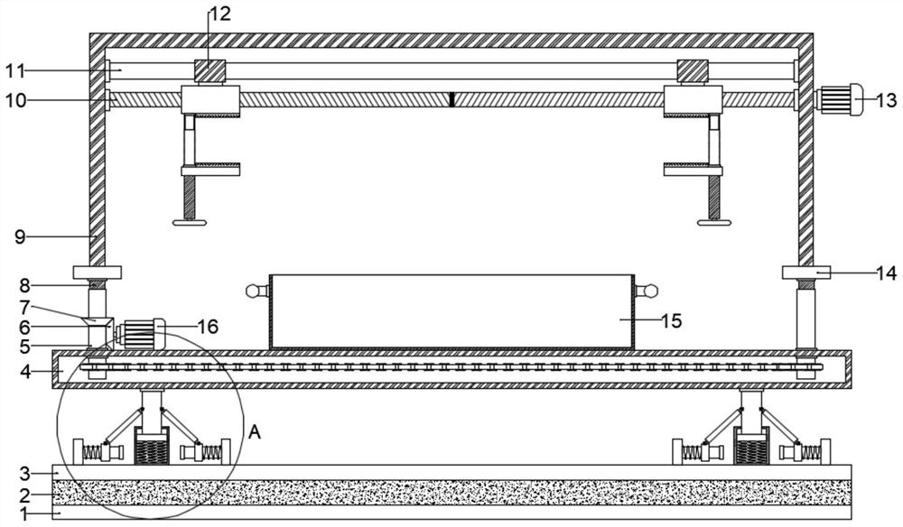
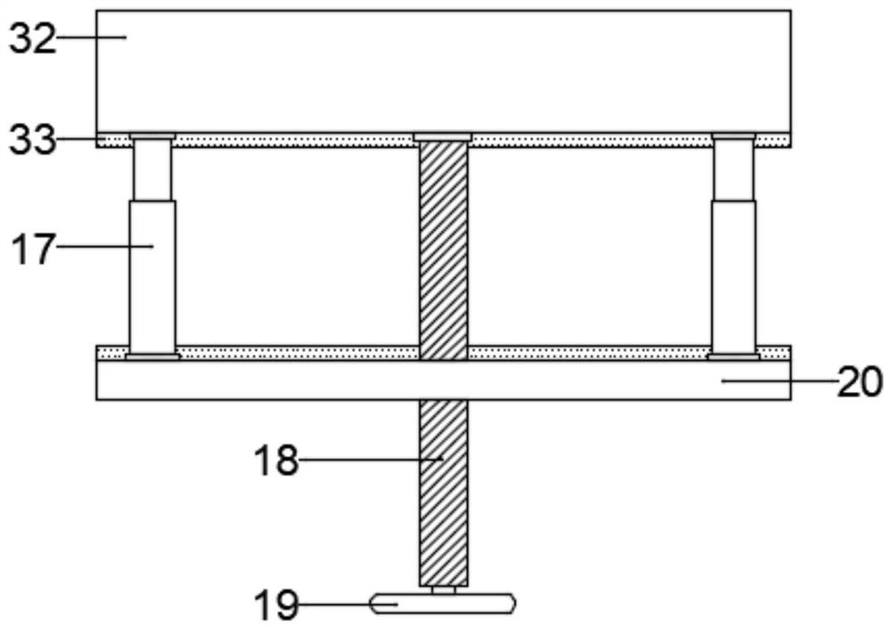
[0022] see Figure 1~3 , in an embodiment of the present invention, a clamping device for medical device processing, comprising a bearing platform 4, a U-shaped plate 9, a shock absorbing unit and a clamping unit, the U-shaped plate 9 is arranged above the bearing platform 4, and the U-shaped There is a lifting assembly between the plate 9 and the loading platform 4. The purpose of setting the lifting assembly is to facilitate the user to adjust the processing area of ​​the parts clamped by the device to a height that is convenient for operation and processing. The clamping unit is located on the U-shaped plate. 9, the damping unit is located at the lower part of the bearing platform 4.

[0023] Lifting assembly comprises two bar-shaped seats 14, and two described bar-shaped seats 14 are respectively arranged on the bottom of U-shaped plate 9, and carrying platform 4 is positioned at the area below two bar-shaped seats 14 and is equidistant from front to back. A plurality of ...

Embodiment 2

[0031] see Figure 4 The difference between this embodiment of the present invention and Embodiment 1 is that further, in order to facilitate the movement of the device, a plurality of moving wheels 34 are symmetrically arranged at the bottom of the shock-absorbing base, and the moving wheels 34 are self-locking rollers. The device can be moved easily and conveniently through the moving wheels 34, which saves time and effort, and is convenient and practical.

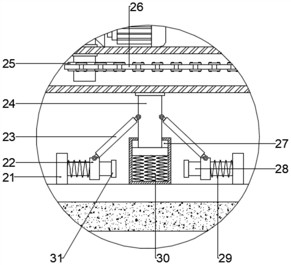
[0032] The working principle of the present invention is: when the present invention is in use, the parts are first clamped and fixed by the clamping unit, and then the parts to be processed are adjusted to a height position convenient for operation and processing by the lifting assembly, and then the parts can be processed During the processing operation, the shock absorbing unit can effectively damp the device and greatly reduce the overall shaking range during processing, so as to avoid affecting the processing accura...


PUM


Abstract

The invention discloses a clamping device for medical instrument machining. The clamping device comprises a bearing table, a U-shaped plate, a damping unit and a clamping unit, wherein the U-shaped plate is arranged above the bearing table; a lifting assembly is arranged between the U-shaped plate and the bearing table; the clamping unit is arranged in the U-shaped plate; and the damping unit is arranged on the lower portion of the bearing table. The device is reasonable in structural layout, the clamping requirements of various parts of different sizes can be met, clamping jaws do not need tobe replaced, time and labor are saved, and excellent damping performance is achieved; and during use, the overall vibration amplitude of the device can be effectively reduced, the situation that themachining precision of the parts is influenced due to too large device shaking is avoided, operation is simple, and use is convenient.

Description

technical field [0001] The invention relates to the technical field of medical device processing and manufacturing, in particular to a clamping device for medical device processing. Background technique [0002] Medical devices refer to instruments, equipment, utensils, in vitro diagnostic reagents and calibrators, materials, and other similar or related items that are used directly or indirectly on the human body for the purpose of diagnosis, prevention, monitoring, treatment or mitigation of diseases, and diagnosis of injuries. , monitoring, treatment, mitigation or functional compensation, examination, replacement, adjustment or support of physiological structures or processes, life support or maintenance, pregnancy control, providing information for medical or diagnostic purposes by examining samples from the human body, At present, medical care has become one of the most concerned things in today's society. [0003] In the process of medical device manufacturing, it is...

Claims


Application Information

Patent Timeline
Patent Type & Authority Applications(China)
IPC IPC(8): B25H1/10B25B11/00
CPCB25B11/00B25H1/10
Inventor 王清弘
Owner 王清弘
Why Eureka
Try Eureka