A large-scale commercial remote sensing satellite platform configuration and assembly method

A technology for remote sensing satellites and satellite platforms, which is applied in the fields of artificial satellites, transportation and packaging, and aerospace vehicles, etc., and can solve problems such as small installation space for stand-alone equipment, large power consumption of remote sensing satellites, and large moment of inertia of the entire star, etc., to achieve improved Support stiffness and overall stability, high structural space utilization, and the effect of reducing the proportion of structural weight

Active Publication Date: 2022-01-07
CHANGGUANG SATELLITE TECH CO LTD
View PDF5 Cites 0 Cited by
  • Summary
  • Abstract
  • Description
  • Claims
  • Application Information

AI Technical Summary

Problems solved by technology

At present, most commercial remote sensing satellite configurations adopt the traditional deck structure. In order to meet the requirements of strength and dynamic characteristics, the main structure of the satellite often makes the structural weight account for a large proportion of the entire satellite, and the rotational inertia of the entire satellite is large, which is not conducive to satellite in-orbit. Fast maneuvering; Most of the remote sensing satellite configurations install the payload in the load cabin, resulting in a small installation space for single equipment in the cabin and poor assembly operability; large remote sensing satellites consume a lot of power and have a high demand for solar array area. Traditional satellite platforms The structure is single, and the installation space of the solar cell array is limited, which is not conducive to the expansion of the area of ​​the solar cell array and the installation of different types of solar cell arrays

Method used


Image

  • A large-scale commercial remote sensing satellite platform configuration and assembly method
  • A large-scale commercial remote sensing satellite platform configuration and assembly method
  • A large-scale commercial remote sensing satellite platform configuration and assembly method

Examples


Embodiment Construction

[0033] It should be noted that, in the case of no conflict, the embodiments of the present invention and the features in the embodiments can be combined with each other.

[0034] The present invention will be described in detail below with reference to the accompanying drawings and examples.

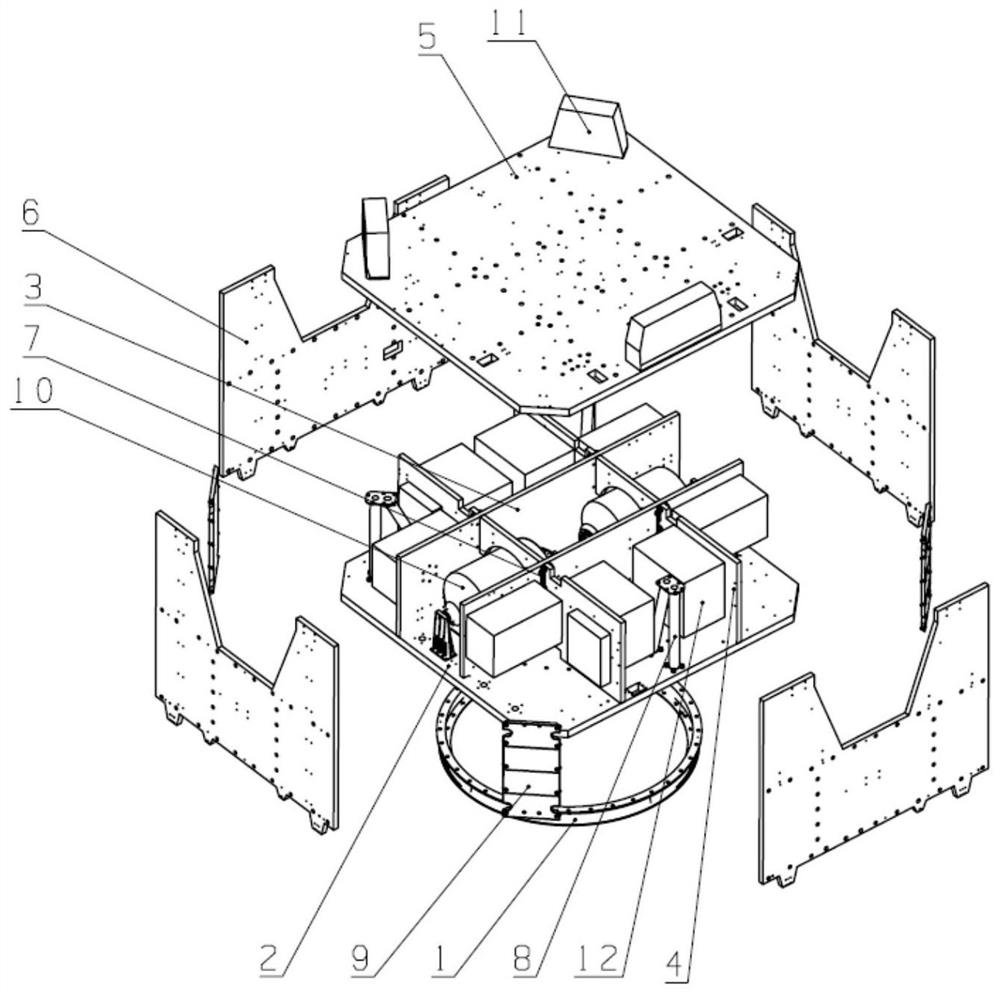
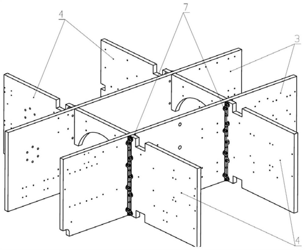
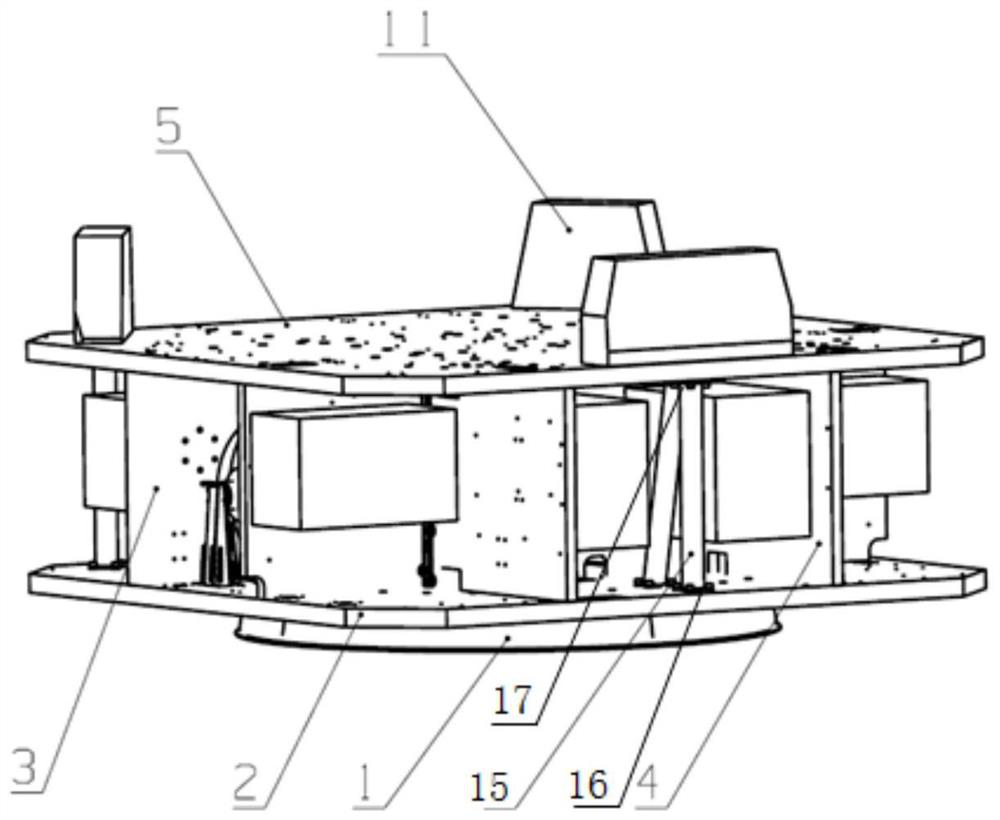
[0035] Such as Figure 1-Figure 5 As shown, a large-scale commercial remote sensing satellite platform configuration, including the main structure of the satellite platform, the docking ring 1 and the solar cell array, the main structure of the satellite platform, the cabin structure composed of carbon fiber panels and aluminum honeycomb sandwich panels and the truss rod assembly Combined way to form a deck-type and truss-type composite structure;

[0036] The main structure of the satellite platform includes a docking plate 2, a tank plate 3, a partition plate 4, a camera plate 5, an outer plate 6, a truss rod assembly 8 and an outer skin 9, and the tank plate 3 and the partition plate...


PUM


Abstract

The invention provides a large-scale commercial remote sensing satellite platform configuration and assembly method. The platform configuration includes a satellite platform main structure, a docking ring and a solar battery array, and the satellite platform main structure includes a docking board, a tank board, a partition board, and a camera board. , the outer plate and the truss rod assembly, the storage tank plate and the partition plate are arranged on the butt plate, the storage tank plate and the partition plate are each provided with multiple pieces, and the vertical and horizontal arrangement forms a well-shaped structure, and the camera plate is set on the well-shaped The upper part of the structure is supported by a number of truss rod components. There are four outer plates arranged around the well-shaped structure. The adjacent two outer plates are connected by the outer skin, and the solar cell array is arranged on the outer surface of the outer plate. , the docking ring is fixed under the docking plate, and the stand-alone equipment of each subsystem is installed on the tank plate and the partition plate; the propulsion subsystem components are installed on the docking plate, and the two tanks are installed symmetrically with respect to the center of mass of the platform. The invention has the advantages of small proportion of structural weight, small inertia, good mechanical properties, good expandability of the area of ​​the solar battery array, and convenient assembly and operation.

Description

technical field [0001] The invention belongs to the technical field of large commercial remote sensing satellites, and in particular relates to a large commercial remote sensing satellite platform configuration and assembly method. Background technique [0002] The overall satellite can be simply divided into two parts: payload and satellite platform. The payload of a satellite is a dedicated device on the satellite. For example, the payload of a remote sensing satellite is an optical camera; the satellite platform is also often called a service module, and its main function is to serve the payload, provide power distribution, attitude control, orbit control, and business measurement and control. etc., to ensure that the satellite can work normally in orbit. At present, most commercial remote sensing satellite configurations adopt the traditional deck structure. In order to meet the requirements of strength and dynamic characteristics, the main structure of the satellite of...

Claims


Application Information

Patent Timeline
Patent Type & Authority Patents(China)
IPC IPC(8): B64G1/10B64G1/22B64G1/44
CPCB64G1/10B64G1/22B64G1/44
Inventor 郑晓峰张雷肖钧凯石有胜谷松高飞
Owner CHANGGUANG SATELLITE TECH CO LTD
Why Eureka
Try Eureka