Ultrahigh vacuum sealing flange structure for non-circular channel of large Tokamak vacuum chamber

A tokamak and ultra-high vacuum technology, applied in the field of tokamak vacuum chamber sealing flange structure, to achieve the effect of improving the ability of anti-vibration and shock, easy processing and maintenance, and improving the reliability of vacuum sealing

Inactive Publication Date: 2020-09-25
SOUTHWESTERN INST OF PHYSICS
View PDF0 Cites 1 Cited by
  • Summary
  • Abstract
  • Description
  • Claims
  • Application Information

AI Technical Summary

Problems solved by technology

[0004] The existing non-circular channel ultra-high vacuum flange sealing technology still has major deficiencies in terms of vacuum sealing reliability when baked at a high temperature of 300 °C, sealing performance under vibration and impact, and structural maintainability.

Method used


Image

  • Ultrahigh vacuum sealing flange structure for non-circular channel of large Tokamak vacuum chamber
  • Ultrahigh vacuum sealing flange structure for non-circular channel of large Tokamak vacuum chamber
  • Ultrahigh vacuum sealing flange structure for non-circular channel of large Tokamak vacuum chamber

Examples


Embodiment Construction

[0028] The present invention will be further described below by means of the accompanying drawings and specific embodiments.

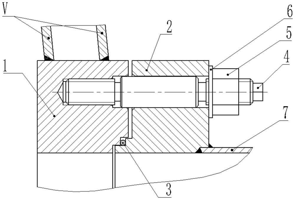
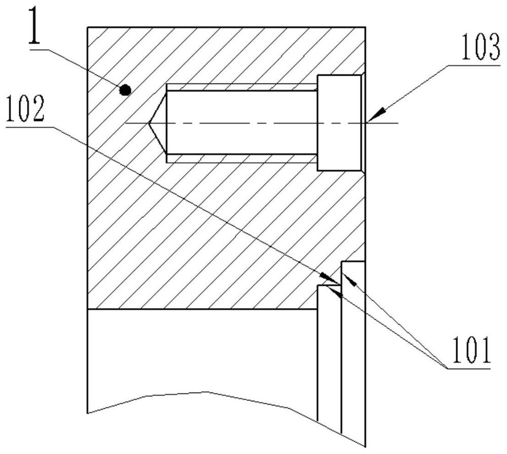
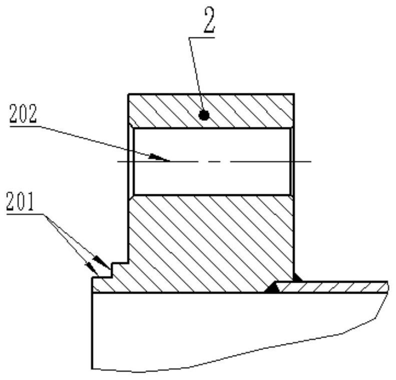
[0029] like figure 1 As shown, the concave flange 1 is welded on the shell of the vacuum chamber V, and the convex flange 2 is welded on the end of the connecting pipe 7 . The entire flange structure can be located in the upper, middle and lower regions of the outer casing of the vacuum chamber. If the connecting pipe of the flange can be drawn out from the neutral position of the coil, the flange structure can also be arranged at the position of the coil.

[0030] The role of connecting pipe 7 is to form an ultra-high vacuum boundary together with the vacuum chamber shell and flange, and to connect plasma diagnosis, heating and vacuum pumping equipment located outside the vacuum chamber of the tokamak device. A flange structure is designed between the vacuum chamber V and the connecting pipe 7 to form an ultra-high vacuum channel.

[0031] The conn...


PUM


Abstract

The invention belongs to the field of magnetic confinement fusion (MCF) technologies, and particularly relates to an ultrahigh vacuum sealing flange structure for a non-circular channel of a large Tokamak vacuum chamber. The structure comprises a concave flange, a convex flange and a connecting pipe. Two matched 90-degree sealing steps are machined on the inner sides of the opposite end faces of the concave flange and the convex flange, and a copper wire ring is placed between the two sealing steps, so that a gap is reserved between the concave flange and the convex flange in the axial direction; and the concave flange and the convex flange are connected through a double-end threaded pin or a double-end stud. By means of the structural mode that the oxygen-free copper wire is compressed through the 90-degree sealing steps, the ultrahigh vacuum sealing requirements of non-circular channel window flanges of different shapes can be met, and the machining and maintaining difficulty of thesealing face of a non-circular window is reduced.

Description

technical field [0001] The invention belongs to the technical field of magnetic confinement nuclear fusion, and in particular relates to a sealing flange structure of a tokamak vacuum chamber. Background technique [0002] With the continuous improvement of the plasma experimental parameters, the tokamak experimental device is developing in the direction of large-scale and precision. The outer diameter of the new-generation tokamak experimental device vacuum chamber container body is greater than 5.2 meters and the height is greater than 3.2 meters. One of its main functions is to provide an ultra-high vacuum environment for the operation of plasma experiments. In order to provide passages for heating, diagnosis, vacuum pumping, lead wires, and material entry and exit, windows of different positions and sizes are opened on the vacuum chamber. The windows adopt a metal sealing flange structure. Must be less than 1×10 -9 Pa·m 3 / s. In order to increase the through-hole are...

Claims


Application Information

Patent Timeline
Patent Type & Authority Applications(China)
IPC IPC(8): G21B1/05G21B1/17
CPCG21B1/057G21B1/17Y02E30/10
Inventor 侯吉来冉红宋斌斌曹曾蔡立君黄运聪唐乐李瑞鋆张炜蔡潇李勇
Owner SOUTHWESTERN INST OF PHYSICS
Why Eureka
Try Eureka