Adhesive bonding mechanism and device

A technology of gluing mechanism and gluing device, applied in sustainable manufacturing/processing, electrochemical generators, electrical components, etc., can solve the problems of high debugging cost, inconvenient operation, complicated disassembly methods, etc. Glue efficiency, reduce debugging work, save time

Pending Publication Date: 2020-09-25
GUANGDONG LYRIC ROBOT INTELLIGENT AUTOMATION CO LTD
View PDF0 Cites 0 Cited by
  • Summary
  • Abstract
  • Description
  • Claims
  • Application Information

AI Technical Summary

Problems solved by technology

[0002] Coating is a process in the production process of lithium-ion batteries. It is to uniformly coat the slurry on the substrate (aluminum foil or copper foil), and some areas on the substrate need to be welded. Therefore, this area is not coated. Cloth treatment, at present, the common practice is to paste the adhesive tape on the area and first coat the entire surface, and then tear off the adhesive tape after coating, while the existing adhesive modules are arranged side by side in the direction of coil material conveying, an

Method used


Image

  • Adhesive bonding mechanism and device
  • Adhesive bonding mechanism and device
  • Adhesive bonding mechanism and device

Examples


Example Embodiment

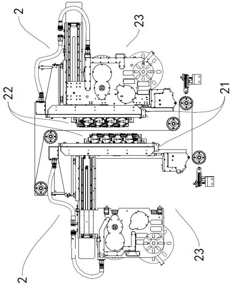
[0021] Various embodiments of the present invention will be disclosed in the drawings below, and for the sake of clarity, many practical details will be described together in the following description. It should be understood, however, that these practical details should not be used to limit the invention. That is, in some embodiments of the invention, these practical details are unnecessary. In addition, for the purpose of simplifying the drawings, some well-known structures and components will be shown in a simple schematic manner in the drawings.

[0022] It should be noted that all directional indications (such as up, down, left, right, front, back, etc.) in the embodiments of the present invention are only used to explain the relationship between various components under a certain posture (as shown in the accompanying drawings). The relative positional relationship, the movement situation, etc., if the specific posture changes, the directional indication also changes acc...


PUM


Abstract

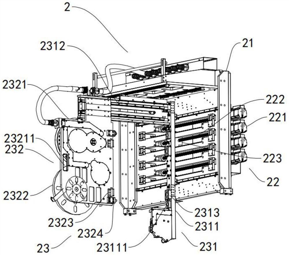
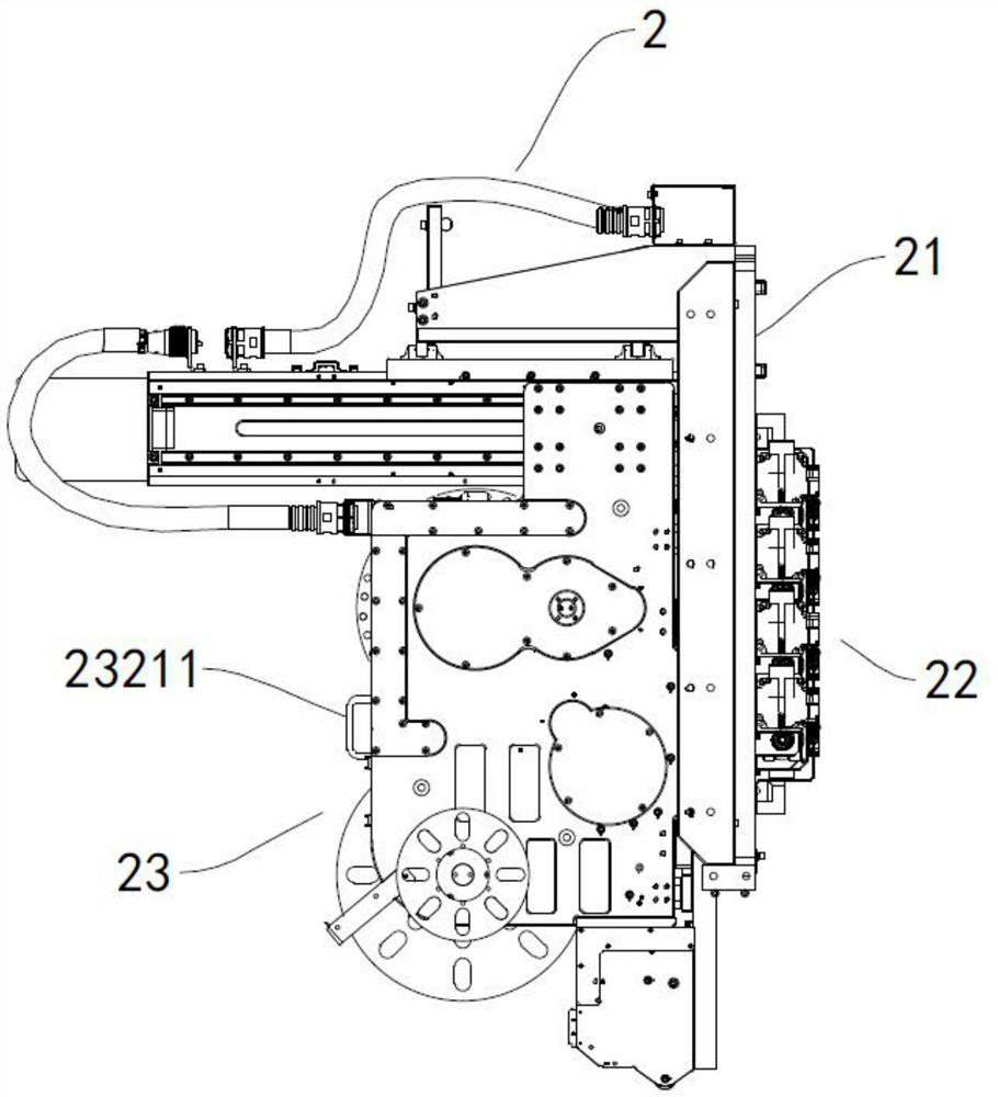
The invention discloses an adhesive bonding mechanism. The adhesive bonding mechanism comprises a fixing assembly and an adhesive bonding assembly; the adhesive bonding assembly is arranged on the fixing assembly; the fixing assembly is used for installing the adhesive bonding assembly; the adhesive bonding assembly can relatively move along the fixing assembly. The invention further provides an adhesive bonding device. The adhesive bonding device is simple in structure; the structure of an existing adhesive bonding mechanism is changed, so that an integrated structure is divided into the fixing assembly and the adhesive bonding assembly; the fixing assembly is used for debugging, and the adhesive bonding assembly is used for replacing and maintaining adhesive paper; since the functions are split, when the adhesive bonding mechanism is abnormal in adhesive bonding, the adhesive bonding assembly is directly pulled out, so that parts can be replaced, the whole adhesive bonding mechanismdoes not need to be detached, and therefore, time is saved, and debugging work after adhesive tapes are replaced is reduced; and in addition, the distance between the adjacent adhesive bonding mechanisms is adjusted through an adjusting mechanism, so that adhesive bonding at different intervals is achieved.

Description

technical field [0001] The invention relates to the technical field of battery production, in particular, to a glue sticking mechanism and device. Background technique [0002] Coating is a process in the production process of lithium ion batteries, which is to uniformly coat the slurry on the substrate (aluminum foil or copper foil), and some areas on the substrate need to be welded, so this area is not coated. At present, the common practice is to apply adhesive tape to the area to coat the whole surface first, and then tear off the adhesive tape after coating, and the existing adhesive tape modules are arranged side by side in the direction of coil conveying, and The disassembly method is complicated. After the disassembly, it takes several debuggings to complete the replacement of the glue sticking module. There are many procedures for replacing the glue sticking module, and the debugging cost is high, and the existing glue replacement is all vertical replacement, that i...

Claims


Application Information

Patent Timeline
IPC IPC(8): H01M10/058H01M10/0525
CPCH01M10/0525H01M10/058Y02E60/10Y02P70/50
Inventor 江茂云柯郁良黄振奎
Owner GUANGDONG LYRIC ROBOT INTELLIGENT AUTOMATION CO LTD
Why Eureka
Try Eureka