Supercharge Your Innovation With Domain-Expert AI Agents!

Self-adaptive leading edge blanking circuit based on high-precision load current detection technology

A technology of load current detection and leading edge blanking, which is applied in the direction of high-efficiency power electronic conversion, electrical components, and adjustment of electrical variables, can solve the problem of inaccurate sampling of knee point voltage, so as to avoid wrong sampling of knee point voltage and reduce light load Power consumption, the effect of avoiding false sampling

Active Publication Date: 2020-09-25
UNIV OF ELECTRONICS SCI & TECH OF CHINA
View PDF12 Cites 5 Cited by
  • Summary
  • Abstract
  • Description
  • Claims
  • Application Information

AI Technical Summary

Problems solved by technology

[0010] Aiming at the inaccurate knee point voltage sampling problem caused by the fixed leading edge blanking time in the knee point voltage detection technology of the above-mentioned primary side feedback flyback converter, the present invention proposes An adaptive leading edge blanking circuit based on high-precision load current detection technology is proposed, which can generate an automatically adjusted adaptive leading edge blanking signal according to the load current and operating frequency of the primary feedback flyback converter to control the primary feedback flyback conversion The knee point voltage sampling of the device can improve the accuracy of the knee point voltage sampling and reduce the power consumption of the circuit

Method used


Image

  • Self-adaptive leading edge blanking circuit based on high-precision load current detection technology
  • Self-adaptive leading edge blanking circuit based on high-precision load current detection technology
  • Self-adaptive leading edge blanking circuit based on high-precision load current detection technology

Examples


Embodiment Construction

[0034] In order to make the public have a deeper understanding of the present invention, a specific embodiment of the present invention will be described and analyzed in detail below in conjunction with the accompanying drawings, and the working principle and practicability of the present invention will be introduced, but the present invention is not limited to this specific embodiment . The present invention covers any modifications, alternative methods and schemes within the spirit and scope of the present invention.

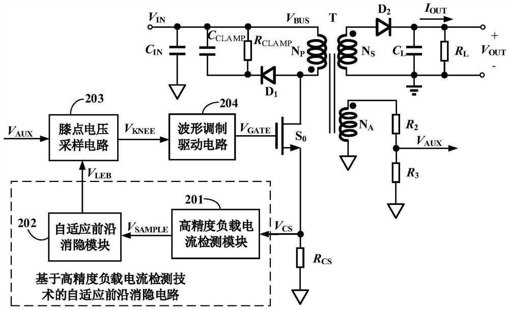
[0035] Such as figure 2 As shown, an adaptive leading edge blanking circuit based on high-precision load current detection technology proposed by the present invention includes a high-precision load current detection module 201 and an adaptive leading edge blanking time setting module 202 . Among them, the high-precision load current detection module 201 is used for the primary side switch tube S of the primary side feedback flyback converter 0 The source s...


PUM


Abstract

The invention discloses a self-adaptive leading edge blanking circuit based on a high-precision load current detection technology. The self-adaptive leading edge blanking circuit comprises a high-precision load current detection module and a self-adaptive leading edge blanking time setting module, wherein the high-precision load current detection module is used for obtaining a signal in direct proportion to the load current and the working frequency of the primary side feedback flyback converter and transmitting the signal to the self-adaptive leading edge blanking time setting module; the self-adaptive leading edge blanking time setting module generates a self-adaptive front blanking signal according to the load current and the working frequency of the primary side feedback flyback converter to control the sampling moment of the knee point voltage; when the primary side feedback flyback converter works under the condition of light load or low frequency, the enabling time of the self-adaptive leading edge blanking signal is shortened, and when the primary side feedback flyback converter works under the condition of heavy load or high frequency, the enabling time of the self-adaptive leading edge blanking signal is prolonged. Error sampling can be avoided, the output voltage precision of the primary side feedback flyback converter is improved, and meanwhile, the light-load powerconsumption of voltage sampling is reduced.

Description

technical field [0001] The invention belongs to the field of integrated circuits and switching power supplies, and more specifically relates to an adaptive leading edge blanking circuit based on high-precision load current detection technology. Background technique [0002] Traditional flyback converter adjustment is mainly divided into primary-side feedback adjustment and secondary-side feedback adjustment. Among them, the secondary-side feedback adjustment method requires optocoupler devices and related circuit components, which increases system cost and has a complex structure. The primary-side feedback adjustment method uses The primary winding or the auxiliary winding is used for feedback adjustment, which has a wider range of applications. Most of the small and medium power flyback converters work in discontinuous mode. By sampling the knee point voltage on the auxiliary winding, the purpose of adjusting the output voltage is achieved, and then the constant voltage out...

Claims


Application Information

Patent Timeline
IPC IPC(8): H02M3/335H02M1/32
CPCH02M3/33523H02M1/32H02M1/0048Y02B70/10
Inventor 罗萍邓成达唐天缘周先立
Owner UNIV OF ELECTRONICS SCI & TECH OF CHINA
Features
  • R&D
  • Intellectual Property
  • Life Sciences
  • Materials
  • Tech Scout
  • Unparalleled Data Quality
  • Higher Quality Content
  • 60% Fewer Hallucinations
Learn More