
Circuit board glue printing device capable of automatically overturning

A technology of automatic flipping and plate printing glue, which is applied in the directions of printed circuit, printed circuit manufacturing, and printed circuit liquid treatment, etc. It is conducive to accurate positioning, improving processing quality, and avoiding the effect of uneven printing

Pending Publication Date: 2020-09-25
何金昌
View PDF2 Cites 7 Cited by
  • Summary
  • Abstract
  • Description
  • Claims
  • Application Information

AI Technical Summary

Problems solved by technology

[0007] 1. The circuit board cannot be turned over automatically. After printing glue on the upper surface of the circuit board, manual assistance is required to turn the lower surface upward, which is time-consuming and laborious, which is not conducive to improving the efficiency of printing glue
[0008] 2. There is no drying mechanism. After the glue is printed, it needs to wait for one end of time for it to solidify, which is inconvenient to turn over. At the same time, the uncured glue is easily caused by external force during the transportation process, which will easily cause the glue to flow around and shift, which will affect the printing. The accuracy of the glue position is not conducive to improving the processing quality and affecting the product quality

Method used


Image

  • Circuit board glue printing device capable of automatically overturning
  • Circuit board glue printing device capable of automatically overturning
  • Circuit board glue printing device capable of automatically overturning

Examples


Embodiment Construction

[0047] The technical solutions of the present invention will be further described below in conjunction with the accompanying drawings and through specific implementation methods.

[0048] Wherein, the accompanying drawings are only for illustrative purposes, showing only schematic diagrams, rather than physical drawings, and should not be construed as limitations on this patent; in order to better illustrate the embodiments of the present invention, some parts of the accompanying drawings will be omitted, Enlarged or reduced, does not represent actual product size.

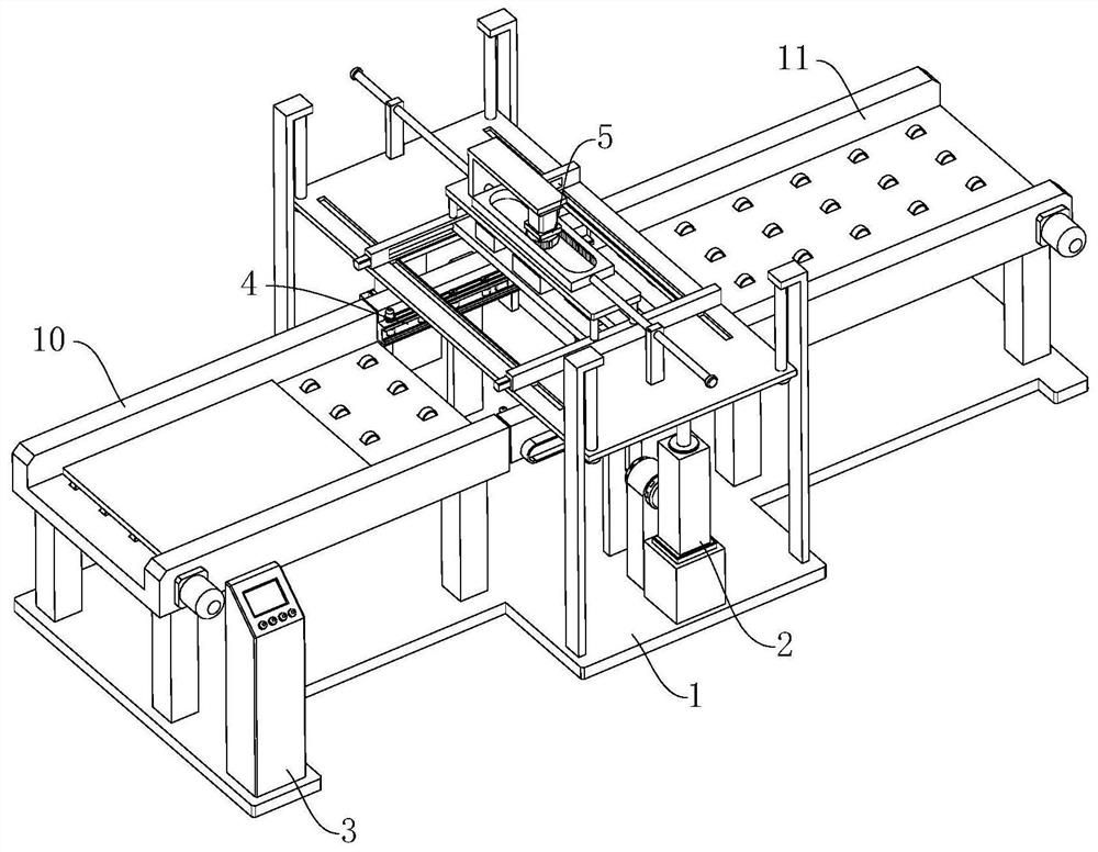
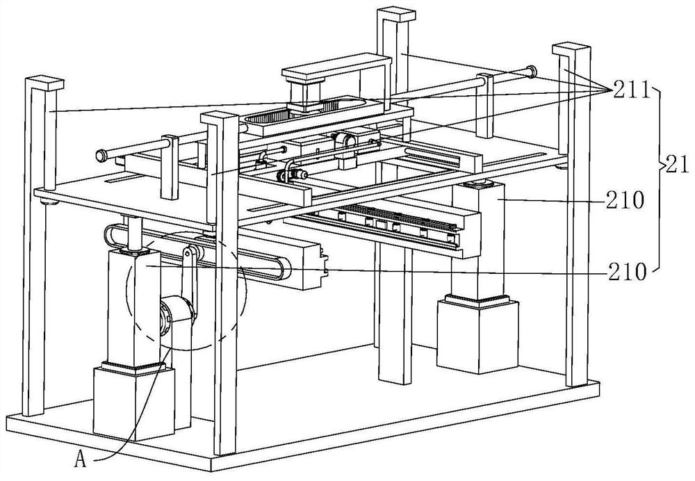
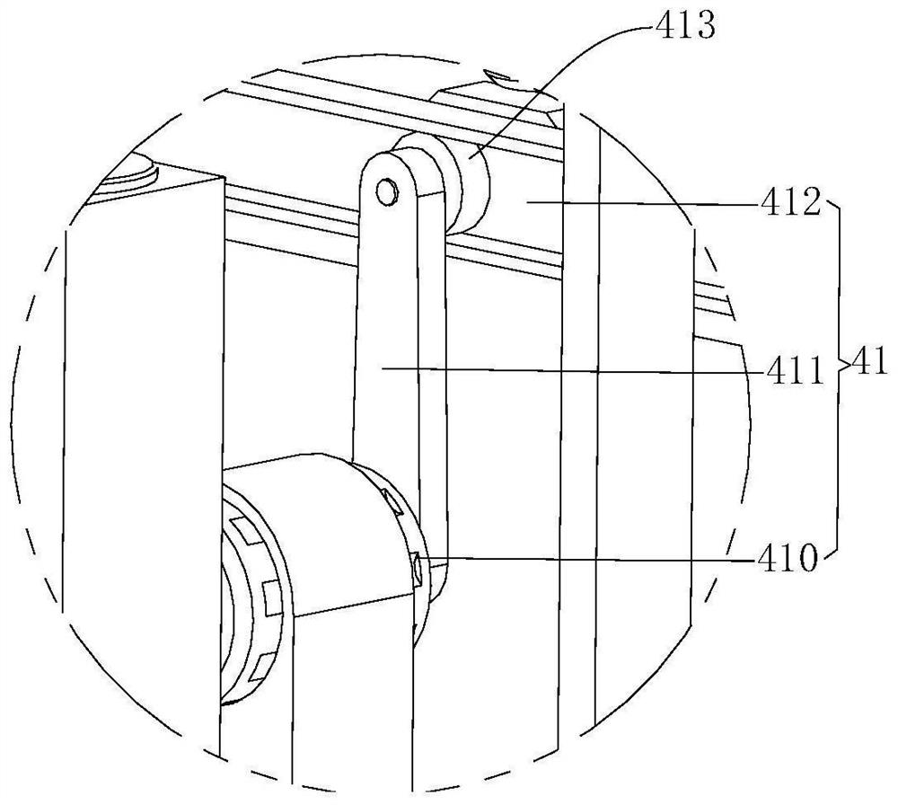
[0049] refer to Figure 1 to Figure 9 A circuit board printing device that can be automatically turned over is shown, including a base 1 and a lifting mechanism 2. The lifting mechanism 2 is arranged on the top of the base 1 to avoid the operation of the turning mechanism 4. The lifting mechanism 2 includes a lifting plate 20 and Jacking assembly 21, described jacking assembly 21 is arranged on the top of base 1,...


PUM


Abstract

The invention relates to the technical field of circuit board dispensing, in particular to a circuit board glue printing device capable of automatically overturning. The device comprises a base and alifting mechanism, and the lifting mechanism comprises a lifting plate and a jacking assembly. The device further comprises a controller, a turnover mechanism and a dispensing mechanism, the turnovermechanism comprises a clamping assembly, a driving assembly and two carrying frames, and the dispensing mechanism comprises a transverse sliding assembly, a longitudinal sliding assembly and a glue injection assembly. A machining groove is formed in the lifting plate, the transverse sliding assembly is arranged at the top of the machining groove, and the longitudinal sliding assembly is arranged at the top of the transverse sliding assembly. The glue injection assembly is fixedly arranged at the top of the transverse sliding assembly, and the jacking assembly, the clamping assembly, the driving assembly, the transverse sliding assembly, the longitudinal sliding assembly and the glue injection assembly are all electrically connected with the controller. According to the circuit board glue printing device capable of automatically overturning and a working method, manual overturning is not needed, the overturning speed is high, meanwhile, the circuit board glue printing device can have arapid drying function and can guarantee the product quality.

Description

technical field [0001] The invention relates to the technical field of circuit board dispensing, in particular to an automatic flipping circuit board glue printing device. Background technique [0002] The names of the circuit boards are: ceramic circuit board, alumina ceramic circuit board, aluminum nitride ceramic circuit board, circuit board, PCB board, aluminum substrate, high frequency board, thick copper board, impedance board, PCB, ultra-thin circuit board, ultra-thin Thin circuit boards, printed (copper etching technology) circuit boards, etc. The circuit board makes the circuit miniaturized and intuitive, and plays an important role in mass production of fixed circuits and optimizing the layout of electrical appliances. [0003] Glue dispensing is a process, also known as sizing, gluing, glue pouring, glue dropping, etc. It is to smear, fill, and drop electronic glue, oil or other liquids on the product, so that the product can stick and fill. Sealing, insulatio...

Claims


Application Information

Patent Timeline
IPC IPC(8): H05K3/00B65G47/248
CPCB65G47/248H05K3/0085
Inventor 何金昌李启同
Owner 何金昌
Learn More