Lung protection equipment for thoracic surgery department

A technology for thoracic surgery and lung protection, applied in life-saving equipment, respiratory protection devices, fire rescue, etc., can solve problems such as low efficiency, unstable gas collection, and inconvenient use

Inactive Publication Date: 2020-09-29
王卫谦
View PDF1 Cites 1 Cited by
  • Summary
  • Abstract
  • Description
  • Claims
  • Application Information

AI Technical Summary

Problems solved by technology

However, this phenomenon also brings disadvantages on the other hand. The diagnosis and treatment of some complex and multi-organ mixed diseases may be neglected. At the same time, in terms of hardware, lung care devices are relatively rare in thoracic surgery. This leads to the slow recovery of patients with lung diseases, which cannot meet the current use requirements. For this reason, people propose a lung protection device for thoracic surgery, such as a lung protection device for thoracic surgery disclosed in Chinese patent CN108159567A. There is a fixed box, the upper end of the fixed box is equipped with a movable box, the upper end of the lifting seat is equipped with a bed board, the upper end of the lifting seat is equipped with a sliding seat, a lung shield is arranged above the bed board, a supporting platform is installed at the front end of the base, and a second Two sliding seats, the second threaded slider is connected to the lifting frame, the lower end of the lifting frame is provided with

Method used


Image

  • Lung protection equipment for thoracic surgery department
  • Lung protection equipment for thoracic surgery department
  • Lung protection equipment for thoracic surgery department

Examples


Embodiment Construction

[0023] The following will clearly and completely describe the technical solutions in the embodiments of the present invention with reference to the accompanying drawings in the embodiments of the present invention. Obviously, the described embodiments are only some, not all, embodiments of the present invention. Based on the embodiments of the present invention, all other embodiments obtained by persons of ordinary skill in the art without making creative efforts belong to the protection scope of the present invention.

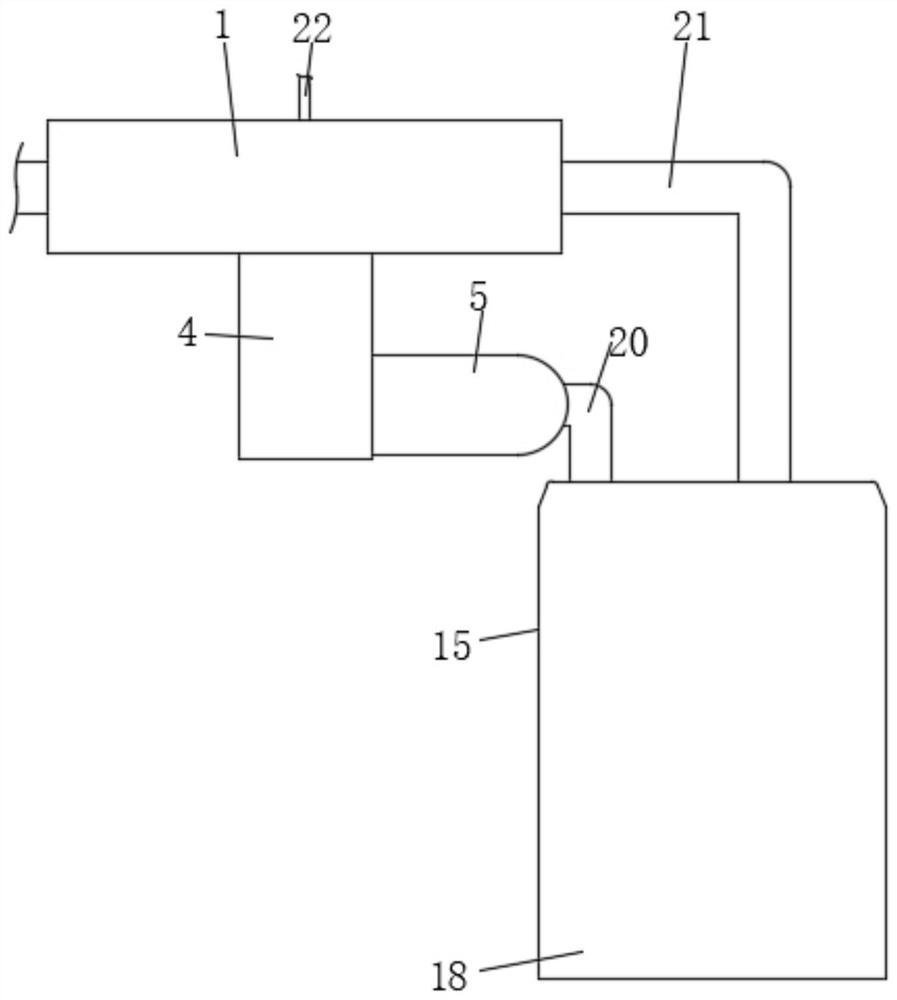
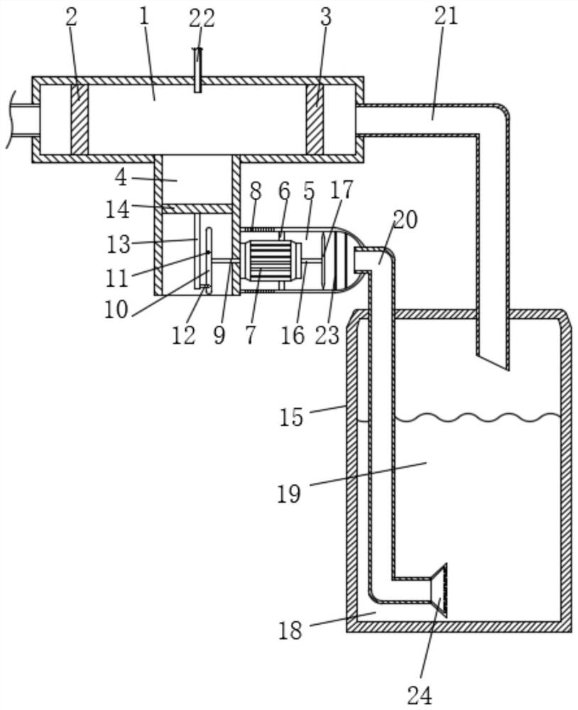
[0024] see Figure 1 to Figure 3 , the present invention provides a technical solution: a lung protection device for thoracic surgery, comprising an air guide tube 1, the upper surface of the air guide tube 1 is provided with a through hole and is fixedly connected with an air delivery tube 3 22 through the through hole, through which the air delivery tube 3 22 Setting, the nursing gas required for nursing can be introduced into the air guide cylinder 1, and t...


PUM


Abstract

The invention discloses lung protection equipment for the thoracic surgery department. The lung protection equipment comprises a gas guide barrel. The inner wall of the gas guide barrel is fixedly connected with a first one-way gas guide valve and a second one-way gas guide valve. A through hole is formed in the lower surface of the gas guide barrel, and the gas guide barrel is fixedly connected with a piston pipe through the through hole. The right side of the piston pipe is fixedly connected with a sleeve. The inner wall of the sleeve is fixedly connected with a reinforcing block. The end, away from the sleeve, of the reinforcing block is fixedly connected with a double-shaft motor. Gas inlet micro holes are formed in the position, close to the left end, of the surface of the sleeve. Theleft end of an output shaft on the double-shaft motor is fixedly connected with a first shaft. By means of the lung protection equipment, through cooperative use between the above structures, the problems that in the actual use process, due to the fact that collection of gas in a traditional mixed gas tank is not stable enough, impurity dust is prone to being carried in gas, running of lung functions of patients is influenced, when collected air cooperates with a humidification and atomization device, the integration degree is not high, efficiency is quite low, and inconvenience is brought touse are solved.

Description

technical field [0001] The invention relates to the technical field of medical equipment, in particular to a lung protection equipment for thoracic surgery. Background technique [0002] Thoracic surgery is a medical specialty that specializes in the study of thoracic organs, mainly referring to the diagnosis and treatment of esophagus, lung, and mediastinal lesions. The field of breast surgery is also included in this specialty, of which pulmonary surgery and esophageal surgery are the main ones; With the improvement of specialization requirements, thoracic surgery has been divided into general thoracic surgery, cardiac surgery, great vessel surgery and pediatric cardiac surgery, etc., which can make specialists more consummate and in-depth in professional knowledge and skills, and the level of specialization also increases. Improve even more. However, this phenomenon also brings disadvantages on the other hand. The diagnosis and treatment of some complex and multi-organ m...

Claims


Application Information

Patent Timeline
IPC IPC(8): A62B7/00A62B7/10A62B9/00
CPCA62B7/00A62B7/10A62B9/00A62B9/003
Inventor 王卫谦
Owner 王卫谦
Why Eureka
Try Eureka