Industrial harmful waste gas treatment device based on VOC biological method

A waste gas treatment device and biological method technology, applied in separation methods, chemical instruments and methods, dispersed particle separation, etc., can solve problems such as inability to effectively deal with waste gas at intake flow rate, and achieve the effect of increasing mass transfer time

Inactive Publication Date: 2020-09-29
施成允
View PDF7 Cites 4 Cited by
  • Summary
  • Abstract
  • Description
  • Claims
  • Application Information

AI Technical Summary

Problems solved by technology

[0005] The purpose of the present invention is to solve the disadvantage that the industrial harmful waste gas treatment device of the VOCs biological method in the prior art cannot effectively treat the waste gas with a large intake flow rate, and proposes an industrial harmful waste gas treatment device based on the VOCs biological method

Method used


Image

  • Industrial harmful waste gas treatment device based on VOC biological method
  • Industrial harmful waste gas treatment device based on VOC biological method
  • Industrial harmful waste gas treatment device based on VOC biological method

Examples


Embodiment 1

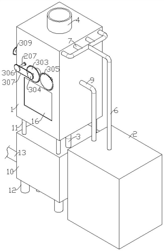
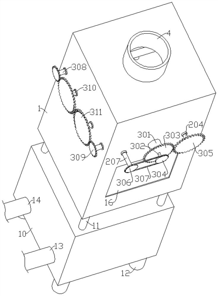
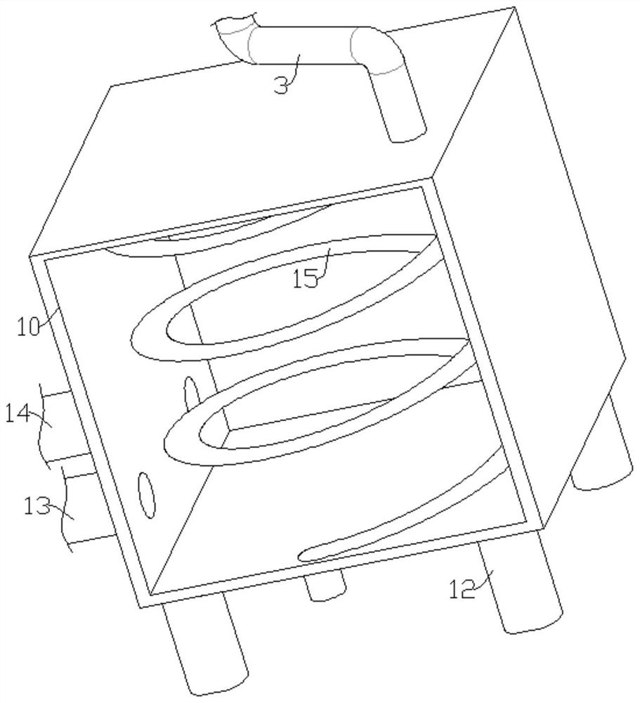
[0022] refer to Figure 1-6, an industrial hazardous waste gas treatment device based on VOCs biological method, including a treatment chamber 1 and an activated sludge chamber 2, the bottom of the treatment chamber 1 is connected with an air inlet pipe 3, the top of the treatment chamber 1 is connected with an outlet pipe 4, and the upper end of the treatment chamber 1 A porous packing layer 5 is provided, a liquid inlet pipe 6 is connected between the treatment chamber 1 and the activated sludge chamber 2, and one end of the liquid inlet pipe 6 is connected with a plurality of liquid inlet manifolds 7, and the liquid inlet manifolds 7 are connected to the treatment chamber 1 The bottom of the liquid inlet manifold 7 located in the treatment chamber 1 is connected with a plurality of evenly distributed nozzles 8, and the nozzles 8 are all located above the porous packing layer 5, and there is a circulation between the treatment chamber 1 and the activated sludge chamber 2. On...

Embodiment 2

[0026] In Embodiment 1, as the device works, the spray liquid gradually accumulates on the top of the first piston 111, and a large amount of spray liquid accumulates on the first piston 111 and affects the normal movement of the first piston 111. Refer to Figure 1-6 , as another preferred embodiment of the present invention, the difference from Embodiment 1 is that the flow guide mechanism includes a liquid collection box 201, the liquid collection box 201 is located between the porous packing layer 5 and the horizontal plate 112, and the liquid collection box 201 and the horizontal plate 112 The plate 112 is fixedly connected, there is a gap between the liquid collection box 201 and the inner wall of the processing chamber 1, and the liquid collection box 201 is provided with an infusion tube 202, the infusion tube 202 communicates with the liquid collection box 201, and one end of the infusion tube 202 communicates with the circulation pipeline 9, The infusion tube 202 is c...


PUM


Abstract

The invention relates to the technical field of waste gas treatment equipment, especially to an industrial harmful waste gas treatment device based on a VOC biological method. The device comprises a treatment chamber and an activated sludge chamber, wherein a porous filler layer is arranged at the inner upper end of the treatment chamber; a liquid inlet pipe is arranged between and communicates with the treatment chamber and the activated sludge chamber; the bottom ends, located in the treatment chamber, of liquid inlet manifolds communicate with a plurality of evenly-distributed spray heads;a heat exchange chamber is arranged at the bottom end of the treatment chamber; and a quantity-controlling gas inlet mechanism is arranged in the treatment chamber. According to the invention, a heatexchange coil and the heat exchange chamber are arranged and matched with each other to cool high-temperature waste gas, so the rising speed of the waste gas in the treatment chamber is reduced, and the mass transfer time of waste gas and spraying liquid is prolonged; and quantitative gas inflow and quantitative gas outflow of large-flow waste gas are achieved by arranging the quantity-controllinggas inlet mechanism.

Description

technical field [0001] The invention relates to the technical field of waste gas treatment equipment, in particular to an industrial harmful waste gas treatment device based on a VOCs biological method. Background technique [0002] The VOCs biological method is a process in which microorganisms attached to the filter medium use the organic components in the exhaust gas as carbon sources and energy sources to maintain their life activities and decompose organic matter into CO2 and H2O under suitable environmental conditions. VOCs (Volatile Organic Compounds) in the main body of the gas phase undergo a mass transfer process from the gas phase to the liquid or solid phase, and then are decomposed by microorganisms in the liquid or solid phase. [0003] Common biological methods for treating VOCs include biological scrubbing. The biological scrubbing process is a suspended activated sludge treatment system consisting of an absorber with inert filler and an activated sludge reac...

Claims


Application Information

Patent Timeline
Patent Type & Authority Applications(China)
IPC IPC(8): B01D53/78B01D53/44
CPCB01D53/44B01D53/78
Inventor 不公告发明人
Owner 施成允
Why Eureka
Try Eureka