
Anaerobic reactor

An anaerobic reactor and reactor technology, applied in the field of anaerobic reactors, can solve the problems of affecting the activity of microbial methanogens in sludge, the decline of methane production, and the reduction of effective reaction area area, so as to alleviate sludge calcification and Pipeline fouling phenomenon, response to changes in water quality and quantity, and the effect of achieving sludge discharge efficiency

Pending Publication Date: 2018-03-27
CHINA ENFI ENGINEERING CORPORATION
View PDF0 Cites 7 Cited by
  • Summary
  • Abstract
  • Description
  • Claims
  • Application Information

AI Technical Summary

Problems solved by technology

[0003] These characteristics of the leachate bring great difficulties to its biological treatment process, among which there are several prominent problems in the anaerobic treatment stage: First, calcium and magnesium ions cause sludge calcification, which in turn affects the microorganisms in the sludge, especially the production Methanogen activity, resulting in decreased methane production
Especially in the anaerobic process with fillers, a large amount of calcium, magnesium ions and suspended solids will easily lead to the enrichment of microorganisms and a large amount of fouling substances at the same time, and they cannot fall off. As time goes by, they will gradually form Sludge compaction, resulting in a large number of dead zones, greatly reducing the effective reaction zone area; secondly, calcium and magnesium form carbonate substances in the process of anaerobic fermentation to produce biogas, as the pH value increases, the solubility decreases, and gradually in the pipeline Crystallization precipitates, resulting in fouling of the pipeline, which reduces the transmission efficiency or even blocks the pipeline, and increases the pipeline pressure to cause safety hazards; moreover, the large fluctuation of water quality and quantity is not conducive to the stable operation of the anaerobic reactor; finally, the leachate inflow is high Suspended solids and biochemical sludge formed anaerobically in the high temperature regulating tank in summer can easily block the water inlet pipes and affect the stable operation of the system

Method used


Image

  • Anaerobic reactor
  • Anaerobic reactor
  • Anaerobic reactor

Examples


Embodiment Construction

[0069] The technical solutions of the present invention will be further described below according to specific embodiments. The protection scope of the present invention is not limited to the following examples, which are listed for illustrative purposes only and do not limit the present invention in any way.

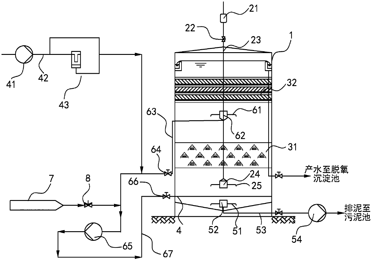
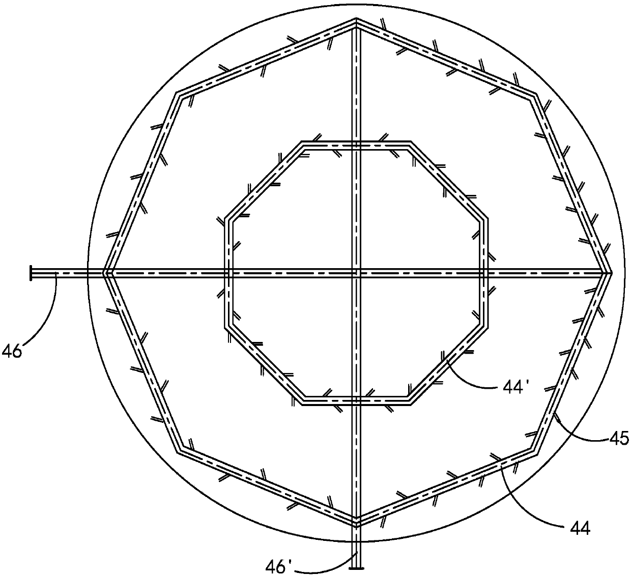
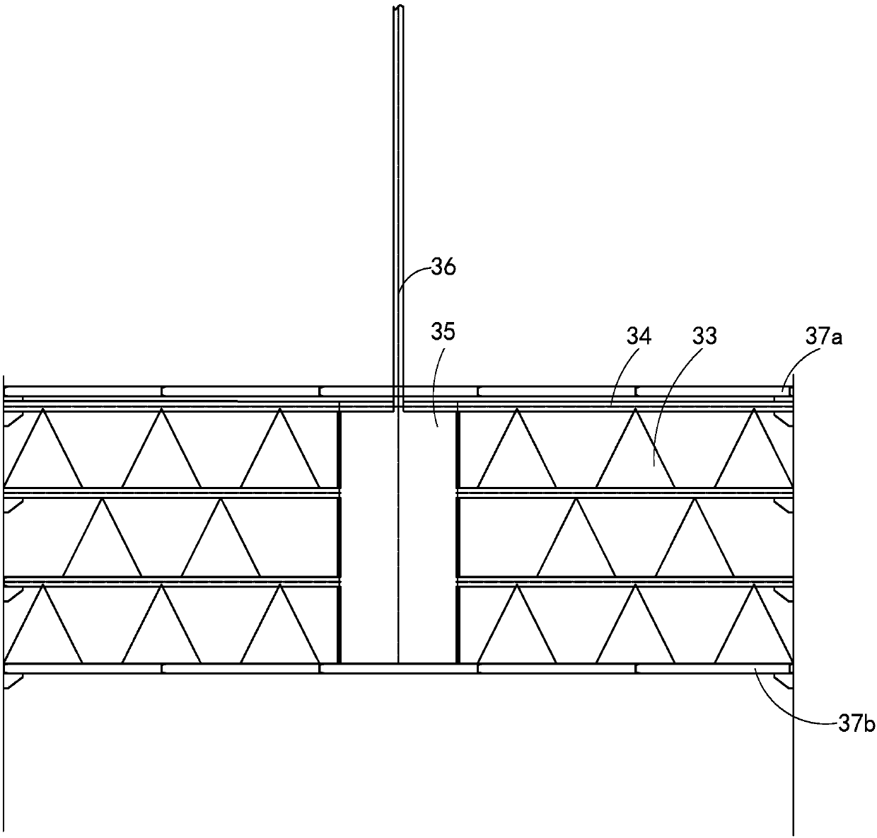
[0070] combine figure 1 , figure 2 , image 3 As shown, the present invention provides an anaerobic reactor, comprising: a reactor tank 1, a gas-liquid separation system, a three-phase separation system, a water distribution system 4 and a sludge discharge system, and the gas-liquid separation system is arranged on the reactor tank body At the top of the reactor, the three-phase separation system is connected to the gas-liquid separation system through the gas header (not shown), and the water distribution system and the sludge discharge system are set at the bottom of the anaerobic reactor.

[0071] The water distribution system includes a water inlet main pipe 42, ...


PUM


Abstract

The invention provides an anaerobic reactor. The anaerobic reactor comprises a reactor tank body, a gas and liquid separating system, a three-phase separating system, a water distribution system and asludge discharging system, wherein the water distribution system comprises a water intake main pipe, a water intake pump and a water distributor; the water distributor is arranged around the bottom part of the reactor tank body, and is a regular polygon-shaped annular water distribution pipe with a plurality of oblique water distribution branch pipes; the oblique water distribution branch pipes are symmetrically crossed along the annular water distribution pipe, so as to form uniformly and symmetrically distributed oblique water distribution ports. The anaerobic reactor has the advantages that by re-designing and optimizing the water distribution system, the sludge discharging system, the gas and liquid separating system and the three-phase separating system of the traditional anaerobic reactor, and arranging an outer circulation system and a temperature control device to adjust the running state of the anaerobic reactor, the adjustability is higher in the percolate anaerobic treatment process, the change of water quality and water quantity can be effectively treated, the dead zone and channeling can be avoided, and the sludge calcification and pipeline scaling are relieved; the percolate treatment process can be efficiently, stably and continuously operate.

Description

technical field [0001] The invention relates to the technical field of wastewater treatment, in particular to an anaerobic reactor for treating wastewater. Background technique [0002] Domestic waste incineration treatment technology has the characteristics of less land occupation, obvious reduction effect, and waste heat can be used, and has been widely used in various countries and regions. The leachate of domestic waste incineration plant is the secondary pollution produced in the process of waste treatment and disposal. The water quantity is characterized by the fact that the amount of leachate produced is closely related to the pre-treatment process of the waste and changes significantly with the seasons. The water quality is characterized by complex and changeable pollutant components. , The water quality changes greatly, and the concentration of organic pollutants, suspended solids and ammonia nitrogen is high, mainly manifested in: high COD concentration (about 4000...

Claims


Application Information

Patent Timeline
IPC IPC(8): C02F3/28C02F103/06
CPCC02F3/28C02F3/2866C02F2303/14C02F2301/046C02F2209/02C02F2203/006C02F2103/06
Inventor 赵永志张计鹏田丽森赵金聂宜文李贝
Owner CHINA ENFI ENGINEERING CORPORATION
Learn More