Supercharge Your Innovation With Domain-Expert AI Agents!

Drilling device for machining cast iron parts

A technology of drilling device and parts, applied in the field of iron casting processing, can solve the problems of easy injury and operator, low work efficiency and high risk factor, and achieve the effect of improving power utilization rate, improving work efficiency and ensuring personal safety.

Inactive Publication Date: 2020-09-29
HANSHAN COUNTY XINGDA DUCTILE IRON FACTORY
View PDF1 Cites 2 Cited by
  • Summary
  • Abstract
  • Description
  • Claims
  • Application Information

AI Technical Summary

Problems solved by technology

However, this device can only process one workpiece at a time, and the work efficiency is low, and the drill chips generated during the drilling process are splashed, which is easy to injure the operator and has a high risk factor

Method used


Image

  • Drilling device for machining cast iron parts
  • Drilling device for machining cast iron parts
  • Drilling device for machining cast iron parts

Examples


Embodiment 1

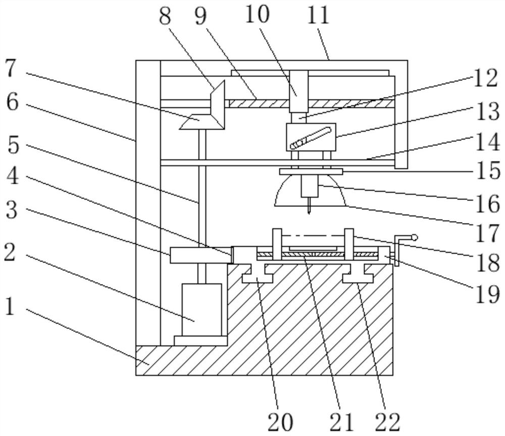
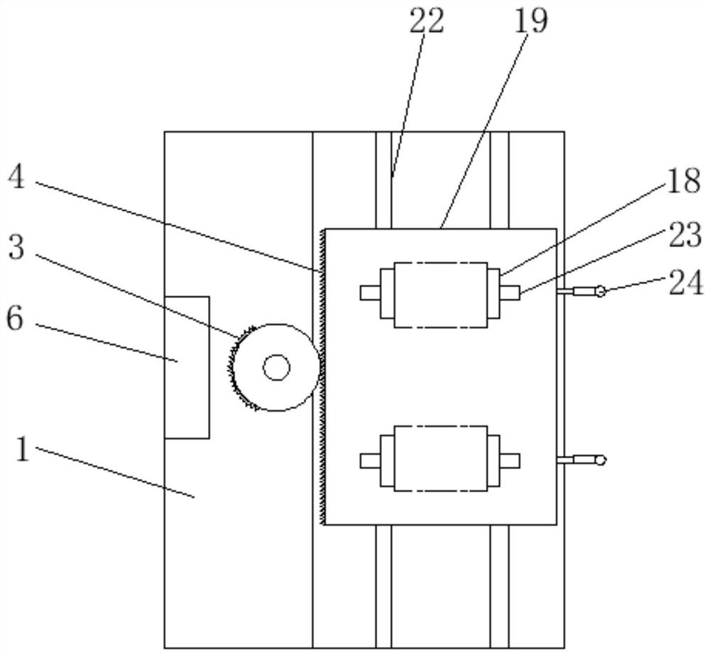
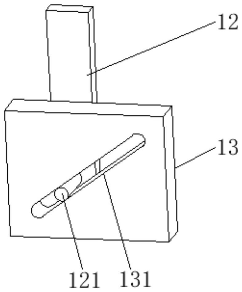
[0022] Embodiment one: refer to Figure 1~3 , in an embodiment of the present invention, a drilling device for processing cast iron parts, including a frame 1, a motor 2 and a column 6 are arranged on the left side of the upper end surface of the frame 1 to provide a power source, and the upper end of the column 6 is fixedly connected to a beam 11. The crossbeam 11 adopts an L-shaped structure, the output end of the motor 2 is fixedly connected with a guide post 5, the end of the guide post 5 close to the motor 2 is connected with a gear 3, and the gear 3 is meshed with a rack 4 to realize the conversion of circular motion into Linear movement, the right end of the rack 4 is fixedly connected with a workbench 19, thereby realizing the reciprocating movement of the workbench 19, the inside of the workbench 19 is provided with a second screw rod 21, and the second screw rod 21 is threadedly connected with a clamping block 18 to realize For the clamping of the workpiece, the clam...

Embodiment 2

[0029] Embodiment 2: This invention also provides another embodiment, which is improved on the basis of the above embodiment. The lower end of the workbench 19 is provided with a slider 20, and the slider 20 is set on the machine. The guide rail 22 on the upper end surface of the frame 1 is moved and connected to the frame 1, and the guide rail 22 adopts a T-shaped cross-section structure to ensure the stability of the reciprocating movement of the workbench 19.

[0030] When the device works, the workpiece is placed on the workbench 19, the handle 24 is turned, and the two-way clamping of the workpiece is realized through the second screw rod 21. At this time, the motor 2 is turned on, and the guide post 5 drives the gear 3 to rotate, and the gear 3 is meshed for transmission. The rack 4 drives the workbench 19 to reciprocate. At the same time, the first bevel gear 7 on the upper end of the guide column 5 engages and drives the second bevel gear 8. Driven by the first screw ro...


PUM


Abstract

The invention discloses a drilling device for machining cast iron parts, and relates to the technical field of cast iron machining. The device comprises a rack. The left side of the upper end surfaceof the rack is provided with a motor and a column. The output end of the motor is fixedly provided with a guide pole. One end, close to the motor, of the guide pole is provided with a gear. A toothedbar is meshed with and transmitted through the gear. The right end of the toothed bar is fixedly provided with a workbench. The inner of the workbench is provided with a second lead screw. Clamping blocks are arranged on the second lead screw in a threaded mode. The clamping blocks pass through the rack through a moving groove arranged on the upper end of the rack. A workpiece is clamped between the clamping blocks. One end, away from the motor, of the guide pole is provided with a first bevel gear. A second bevel gear is meshed with and transmitted through the first bevel gear. The device candrill and take parts at the same time to improve the work efficiency. A same power source motor drives the workbench to reciprocate and the drilling machine up and down to improve the power utilization rate. At the same time, a protective cover effectively prevents drilling waste from splashing, effectively ensuring the personal safety of operators.

Description

technical field [0001] The invention relates to the technical field of cast iron processing, in particular to a drilling device for processing cast iron parts. Background technique [0002] Castings are metal shaped objects obtained by various casting methods, that is, the smelted liquid metal is poured into the pre-prepared mold by pouring, injection, suction or other casting methods, and after cooling, it is polished and other subsequent processing methods , The obtained objects have a certain shape, size and performance. Similarly, iron castings are objects cast from molten iron. [0003] In the prior art, the machining and forming of the holes mostly adopts the drilling process. When drilling for cast iron parts, the positioning of the drilling position and the fixation of the workpiece will affect the drilling quality. The prior art discloses a drilling device with an application number of 201920722082.9 for processing cast iron parts, including a processing platform ...

Claims


Application Information

Patent Timeline
IPC IPC(8): B23B39/00B23B47/20B23Q3/06B23Q11/08
CPCB23B39/00B23Q3/06B23Q5/40B23Q11/08
Inventor 张福新
Owner HANSHAN COUNTY XINGDA DUCTILE IRON FACTORY
Features
  • R&D
  • Intellectual Property
  • Life Sciences
  • Materials
  • Tech Scout
  • Unparalleled Data Quality
  • Higher Quality Content
  • 60% Fewer Hallucinations
Learn More