Water storage tank
A water storage tank and tank body technology, applied in the field of water storage tanks, can solve the problems that the pH value and nutrient concentration of the water body of the water storage tank cannot be adjusted, the effect of plant growth is affected, the effect of cleaning is poor, etc., so as to improve the growth effect, Easy to transport, discharge and clean up
- Summary
- Abstract
- Description
- Claims
- Application Information
AI Technical Summary
Problems solved by technology
Method used
Image
Examples
Embodiment 1
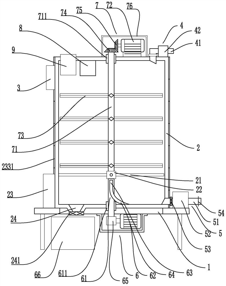
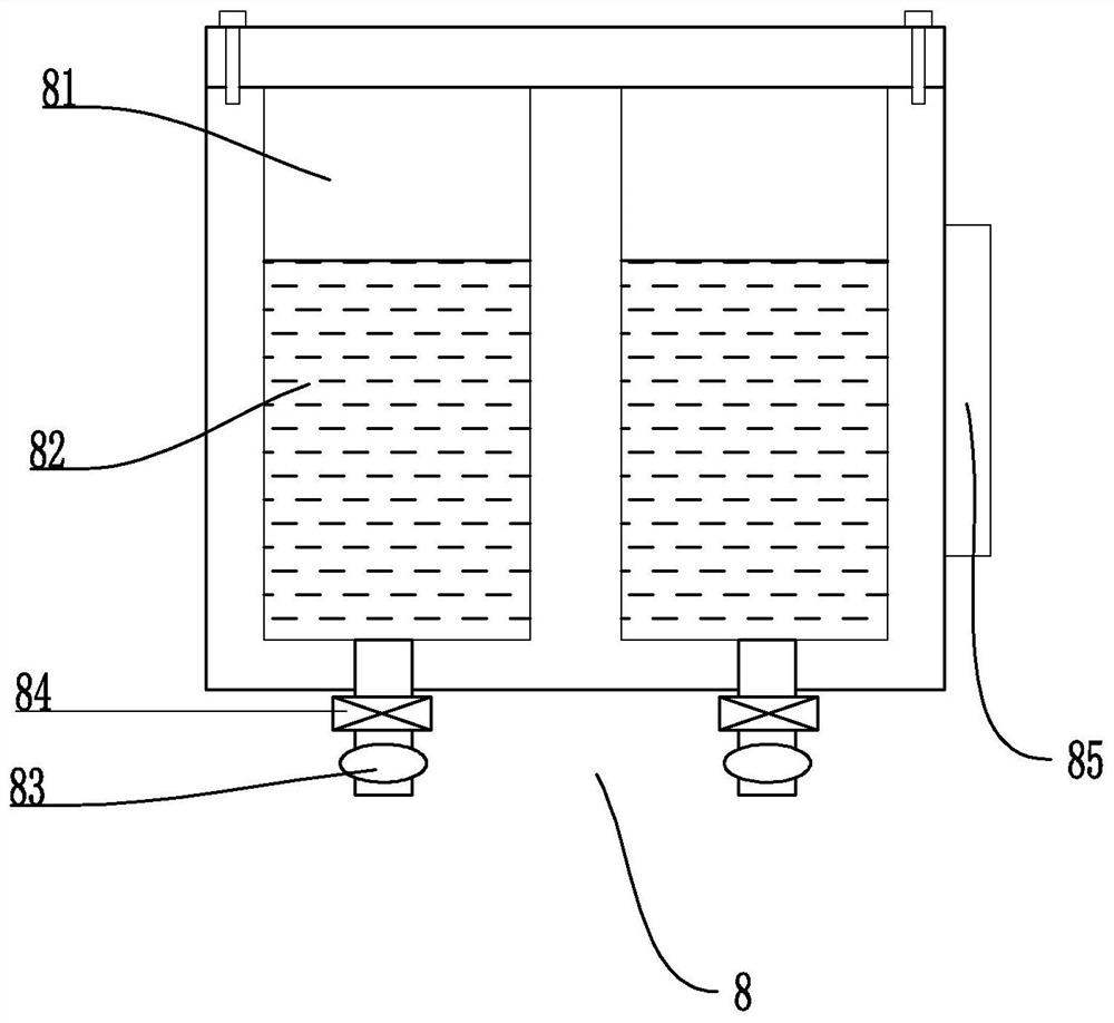
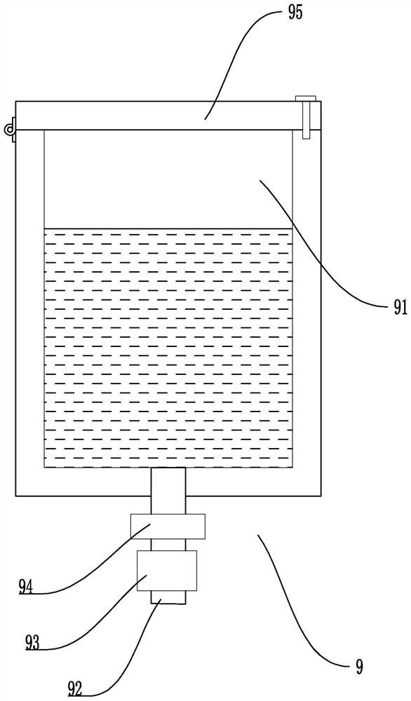
[0038] Embodiment 1, this embodiment discloses a water storage tank, such as Figures 1 to 5 As shown, it includes a base 1 and a tank body 2 fixed on the base 1, the tank body 2 is fixed with a controller 3, and the upper and lower ends of the tank body 2 are respectively provided with a water inlet device 4 and a water outlet device 5, The bottom of the tank body 2 is provided with a cleaning device 6 adapted thereto. The cleaning device 6 includes a cleaning shaft 61 and a cleaning motor 62 adapted to the cleaning shaft 61. The cleaning shaft 61 is provided with a cleaning blade fixedly connected thereto. The cross-section of the cleaning blade is set in a J-shaped structure. The cleaning blade includes an integrated cleaning baffle 63 and a cleaning scraper 64. The lower end of the cleaning shaft 61 runs through the bottom of the tank body 2 and it passes through the sleeve of the first bearing structure 611 and the cleaning scraper 64. The tank body 2 is connected with ea...
Embodiment 2
[0047] Embodiment two, such as Figure 6 As shown, in this embodiment, on the basis of implementation one, the upper end of the cleaning box 66 is fixedly connected with the cleaning port 24 by setting the cleaning pipe 661, and the upper end of the cleaning box 66 is also provided with an exhaust fan 662 that is compatible with it. , the exhaust fan 662 is fixedly connected to the cleaning box 66 through the exhaust pipe 663, and the exhaust filter 664 is also arranged at the junction of the exhaust pipe 663 and the cleaning box 66; Impurities are sucked into the cleaning box 66, and the air exhaust filter screen 664 prevents the sludge impurities in the cleaning box 66 from entering the exhaust fan 662 and then affecting the normal operation of the exhaust fan 662.
[0048] Its working process is as follows: On the basis of the working process of Embodiment 1, the exhaust fan 662 draws air to the cleaning box 66 through the exhaust pipe 663, so that a negative pressure is fo...
Embodiment 3
[0049] Embodiment three, such as Figure 7 As shown, this embodiment is based on the second embodiment, and the cleaning box 66 is also provided with a press-fit structure 67 that is compatible with it. The press-fit structure 67 includes a matched press-fit baffle 671 and a press-fit Close the electric cylinder 672, the piston rod of the press electric cylinder 672 and the press baffle 671 are fixedly connected to each other, and the side of the cleaning box 66 is also provided with a dodge door 665 that is compatible with the press baffle 671, and the dodge door 665 passes through the bolt The method is detachably connected with the cleaning box 66; the pressing structure 67 drives the pressing baffle 671 through the pressing electric cylinder 672 to squeeze and compress the sludge and impurities in the cleaning box 66 to reduce the volume of waste materials, and by setting the movable door 665 is used for taking out the waste material in the cleaning box 66 to facilitate th...
PUM
 Abstract
Description
Claims
Application Information
 - R&D
- Intellectual Property
- Life Sciences
- Materials
- Tech Scout
- Unparalleled Data Quality
- Higher Quality Content
- 60% Fewer Hallucinations
Browse by: Latest US Patents, China's latest patents, Technical Efficacy Thesaurus, Application Domain, Technology Topic, Popular Technical Reports.
© 2025 PatSnap. All rights reserved.Legal|Privacy policy|Modern Slavery Act Transparency Statement|Sitemap|About US| Contact US: help@patsnap.com


