A rainwater kinetic energy and wind energy collection power generation device

A power generation device and kinetic energy technology, which is applied in the direction of wind energy generation, generator/motor, wind turbine and water energy converter, etc. The effect of clever design, low energy harvesting efficiency and high energy harvesting efficiency

Active Publication Date: 2021-07-02
SOUTHWEST JIAOTONG UNIV
View PDF6 Cites 0 Cited by
  • Summary
  • Abstract
  • Description
  • Claims
  • Application Information

AI Technical Summary

Problems solved by technology

[0003] According to the search, there are already some rainwater energy collection devices, such as "a solar street lamp with a wide range of application for smart cities" disclosed in Chinese patent application number 2019109714461. For rainwater power generation, the collection efficiency and energy utilization rate are low, and the device is mainly used for street lamps, which collects less energy and is difficult to recover the cost
Another example is "a new type of rainwater power generation device" disclosed in Chinese Patent Application No. 2019103157498. This device hits the impeller mechanism in the pipeline structure through rainwater, and then connects the rotating shaft of the impeller part to the generator through the transmission equipment to generate electricity. Energy loss Too many, and the application area is narrow, the development prospect is not ideal
And Chinese Patent Application No. 2018110403986 discloses "a bus station for collecting and filtering rainwater power generation", which transports rainwater to hydroelectric power generation devices through underground water pipelines for power generation. The project is complicated and the results are not optimistic.

Method used


Image

  • A rainwater kinetic energy and wind energy collection power generation device
  • A rainwater kinetic energy and wind energy collection power generation device
  • A rainwater kinetic energy and wind energy collection power generation device

Examples


Embodiment Construction

[0024] The present invention will be further described in detail below in conjunction with the accompanying drawings and specific embodiments.

[0025] The object of the present invention is to provide a rainwater kinetic energy and wind energy collection power generation device, which can effectively complete the collection of rainwater kinetic energy and wind energy and complete power generation.

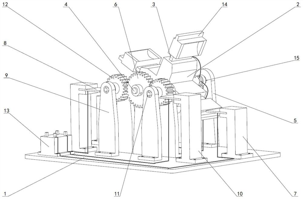
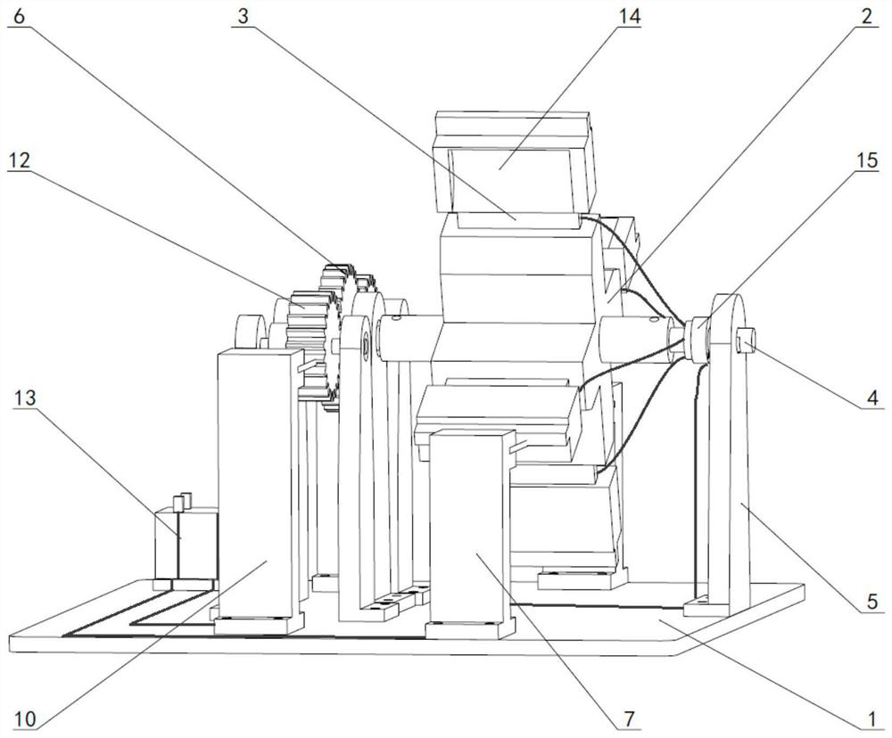
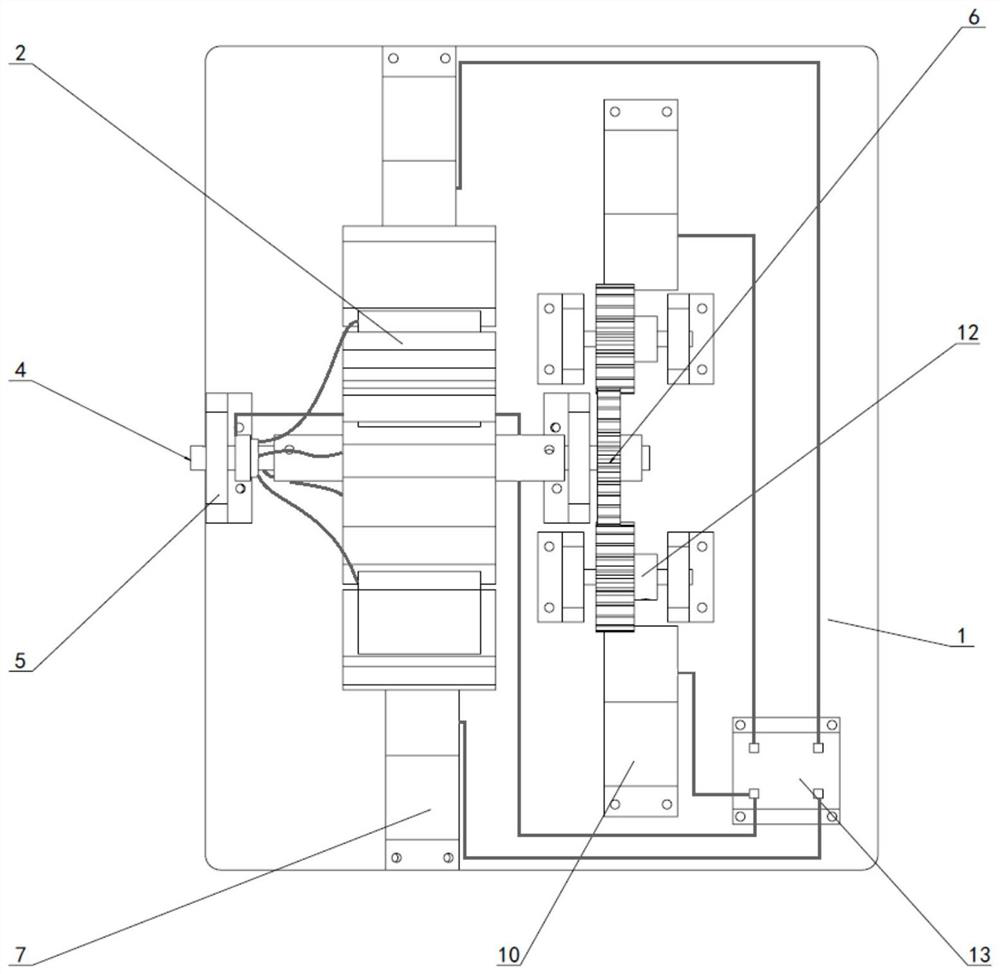
[0026] The purpose of the present invention is achieved through the following technical solutions: a rainwater kinetic energy and wind energy collection power generation device, including a base plate 1 and a hydraulic turret 2, the middle and one side of the rectangular base plate 1 are respectively provided with coaxial spindle supports 5. The main shaft support 5 is an "L"-shaped structure, and its bottom is fixed to the rectangular bottom plate 1 by bolts. The shoulders at both ends of the main shaft 4 of the stepped shaft structure and the main shaft support 5 are fixed by the...


PUM


Abstract

The invention provides a rainwater kinetic energy and wind energy collection power generation device, which belongs to the technical field of small power generation equipment. The main shaft support is an "L" shaped structure, the bottom of which is fixed to the rectangular bottom plate by bolts, the shoulders at both ends of the main shaft of the stepped shaft structure and the main shaft support are fixed by the outer ring of the bearing, and the large gear is fixed on one end of the main shaft by a flat key. The other side of the main shaft is respectively provided with meshing pinion gears, the other end of the main shaft is fixed by the top wire and the conductive slip ring, the four ends of the "cross-shaped" structure are provided with waterwheel piezoelectric plates, and the protruding part of the main support is provided with There are ordinary piezoelectric sheets; the two sides of the axis supported by the main shaft in the middle are respectively provided with pinion shaft supports, and the two ends of the pinion shaft are respectively fixed with the pinion shaft supports through the outer ring of the bearing; the rectangular bottom plate is along the radial direction of the pinion Both ends are provided with auxiliary supports, and the inward protruding part of the auxiliary supports is provided with ordinary piezoelectric sheets; the supercapacitor is fixed by a rectangular bottom plate with bolts.

Description

technical field [0001] The invention belongs to the technical field of small power generation equipment. Background technique [0002] With the increasing energy crisis and environmental pollution, the development and utilization of renewable energy has become the focus. At present, the more reasonable utilization of secondary energy recognized in the world is electricity, which is more environmentally friendly, the most versatile, and the most convenient to use compared to the direct utilization of fossil fuels. Due to the relatively mature development of the power system at this stage, how to further develop and utilize primary energy, that is, various energies and resources directly obtained from nature without processing and transformation, is very important. So far, human beings have been able to generate electricity through water energy, wind energy, chemical energy, solar energy and nuclear energy. But in nature, there are other sources of energy that are worth harn...

Claims


Application Information

Patent Timeline
Patent Type & Authority Patents(China)
IPC IPC(8): F03B13/00F03D9/11H02N2/18
CPCF03B13/00F03D9/008F05B2220/706F03D9/11H02N2/183H02N2/185Y02E10/72Y02E70/30
Inventor 张祖涛张庭生何雨宸张超郗凯孙一鸣安宣谕潘亚嘉
Owner SOUTHWEST JIAOTONG UNIV
Why Eureka
Try Eureka