Novel voltage sag severity evaluation method

A technology of voltage sag and severity, which is applied in the field of new-type voltage sag severity evaluation, can solve the problem of not considering the sensitivity of equipment to voltage sag events, and achieve the effect of high evaluation accuracy

Active Publication Date: 2020-09-29
STATE GRID SICHUAN ELECTRIC POWER CORP ELECTRIC POWER RES INST
View PDF7 Cites 6 Cited by
  • Summary
  • Abstract
  • Description
  • Claims
  • Application Information

AI Technical Summary

Problems solved by technology

[0006] The technical problem to be solved by the present invention is that in the methods for evaluating the severity of voltage sag events in the prior art, most indicators do not consider the sensitivity of equipment to voltage sag events, and evaluate the severity of voltage sags based on the characteristics of a single event , such indicators fail to fully link the voltage sag with the industrial process and other issues

Method used


Image

  • Novel voltage sag severity evaluation method
  • Novel voltage sag severity evaluation method
  • Novel voltage sag severity evaluation method

Examples


Embodiment 1

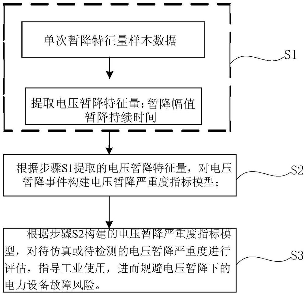
[0039] Such as figure 1 As shown, a novel method for evaluating the severity of voltage sags according to the present invention includes the following steps:

[0040] S1: Extract the voltage sag characteristic quantity based on the sample data of the single voltage sag characteristic quantity; among them, the voltage sag characteristic quantity includes the sag amplitude and the sag duration;

[0041] S2: According to the voltage sag characteristic quantity extracted in step S1, construct a voltage sag severity index model for the voltage sag event: when the corresponding value of the sag is in the insensitive area, the voltage sag severity is 0; When the corresponding value of the drop is in the sensitive area, the formula used in the voltage sag severity index model is as follows:

[0042]

[0043] Where Indicates the severity index of voltage sag, subscript B ij J and i represent the j-th sag at bus i; C w Indicates the voltage sag tolerance curve used for evaluation; y represen...

Embodiment 2

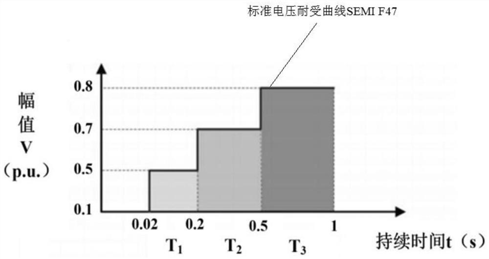
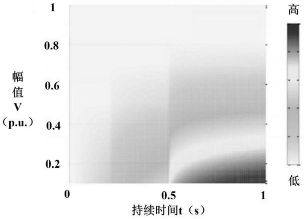
[0058] Such as Figure 1 to Figure 7 As shown, the difference between this embodiment and Embodiment 1 is that considering that the existing severity index of a voltage sag event does not fully reflect the sensitivity trend of the device's response to a voltage sag, it is difficult to achieve the change from one severity to another. The degree of gradual transition. In fact, due to many factors that affect the sensitivity of equipment to voltage sags, the boundary between equipment tripping and crossing cannot be defined by open wires. SSI accurately describes the gradual transition from one severity level to another. In order to reflect the flexibility and capability of SSI, on the basis of embodiment 1, in step S2, the formula used by the voltage sag severity index model is as follows:

[0059]

[0060] Where Indicates the severity index of voltage sag, subscript B ij J and i represent the j-th sag at bus i; C w Indicates the voltage sag tolerance curve used for evaluation; ...


PUM


Abstract

The invention discloses a novel voltage sag severity evaluation method, which comprises the steps: S1, extracting a voltage sag characteristic quantity according to single voltage sag characteristic quantity sample data; S2, constructing a voltage sag severity index SSI model for a voltage sag event; and S3, according to the constructed index model, evaluating the severity of the voltage sag to besimulated or detected, guiding industrial use, and further avoiding the power equipment fault risk under the voltage sag. Compared with the existing single event characteristic, the method provided by the invention better reflects the uncertainty of the response of the equipment to the voltage sag; according to the method, the change of equipment sensitivity is fully explained by changing parameter setting in an SSI formula, and an SSI equivalent contour line is determined by setting parameters in the SSI formula; according to the voltage sag severity index model constructed in the method, the sensitivity degree of the equipment to the voltage sag event is considered, and the index can fully and tightly connect the voltage sag with the industrial process.

Description

Technical field [0001] The invention relates to the technical field of voltage sags, in particular to a novel method for evaluating the severity of voltage sags. Background technique [0002] In the process of understanding voltage sag in China, the national standard GB / T30137-2013 "Power Quality Voltage Sag and Short-term Interruption" was promulgated in December 2013, which defined voltage sag as: a certain point in the power system. The voltage root mean square value suddenly drops to 0.1pu~0.9pu, and returns to normal after a short duration of 10ms~1min. Due to the frequent interruption of industrial processes and the breakdown of electronic equipment, voltage sags have caused huge economic losses to many utilities and industries. Voltage sag is one of the most critical issues in power quality, and sag severity assessment has always been a research hotspot in the field of power quality. As a key step of voltage sag compensation, it is necessary to accurately assess the seve...

Claims


Application Information

Patent Timeline
Patent Type & Authority Applications(China)
IPC IPC(8): G01R19/165G01R31/00
CPCG01R19/16576G01R31/00
Inventor 徐琳刘畅杨华魏巍
Owner STATE GRID SICHUAN ELECTRIC POWER CORP ELECTRIC POWER RES INST
Why Eureka
Try Eureka