A prediction and early warning method of piping development based on dynamic tomographic scanning

A technology of tomographic scanning and piping, which is applied in the field of formation lithology, geological structure and geophysical exploration, can solve the problems of lack of monitoring data and piping quantitative relationship, and achieve the effect of precise positioning and improvement

Active Publication Date: 2022-07-01
CHONGQING JIAOTONG UNIVERSITY
View PDF0 Cites 0 Cited by
  • Summary
  • Abstract
  • Description
  • Claims
  • Application Information

AI Technical Summary

Problems solved by technology

However, in the monitoring process, due to the lack of quantitative relationship between monitoring data and piping development, only qualitative analysis can be made based on data distribution and change rules

Method used


Image

  • A prediction and early warning method of piping development based on dynamic tomographic scanning
  • A prediction and early warning method of piping development based on dynamic tomographic scanning
  • A prediction and early warning method of piping development based on dynamic tomographic scanning

Examples


Embodiment 1

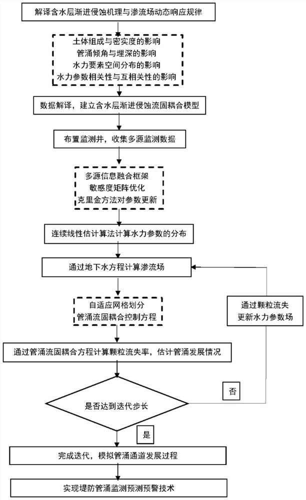
[0060] see figure 1 The present embodiment discloses a method for predicting and early warning of piping development based on dynamic tomographic scanning, which includes the following steps:

[0061] 1) Interpret the progressive erosion mechanism of the aquifer and the dynamic response law of the seepage field; interpret the relationship between the aquifer parameters and hydraulic elements in the process of piping development; interpret the influence of the autocorrelation and cross-correlation of aquifer parameters on the data time series response ;

[0062] 2) Automatically identify the subdivision of the aquifer at the base of the embankment, and use the mass conservation, momentum conservation and energy conservation in the process of material transport to explain the relationship between water flow and particle motion in different subdivisions;

[0063] 3) Arranging monitoring wells in the monitoring area to collect monitoring data: arranging monitoring wells in the mo...

Embodiment 2

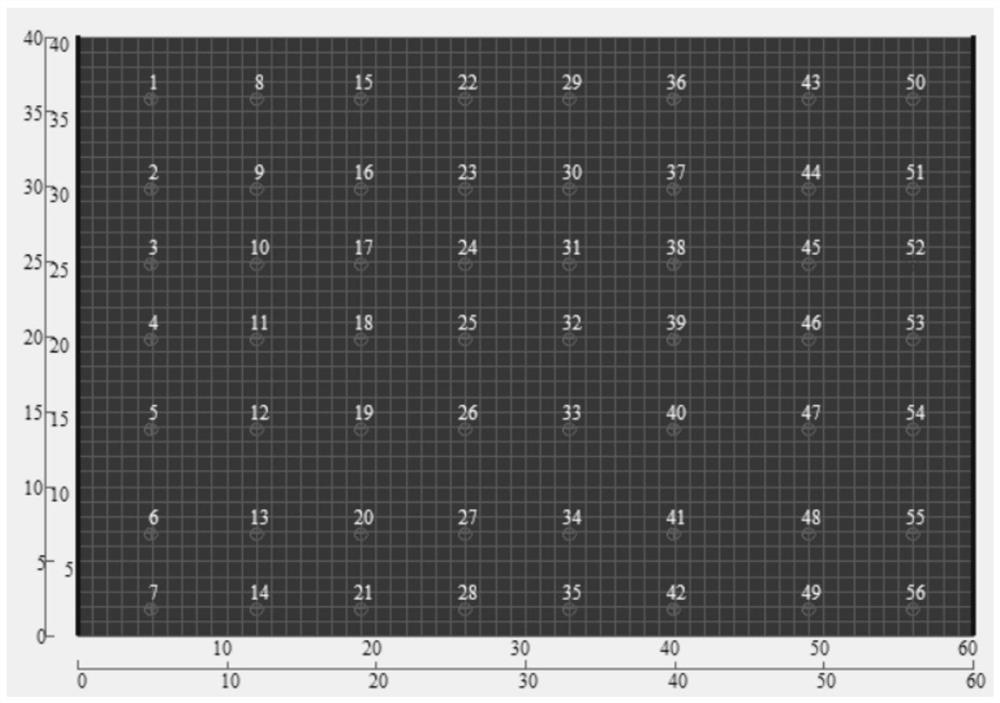
[0108] The main steps of this example are the same as those of Example 1. Further, an aquifer area of ​​40m×60m is selected as the study area and numerically modeled, and the permeability coefficient distribution of the aquifer is characterized by the tomographic scanning method. It is assumed that there is a high head area on the left boundary of the model, which is the water level boundary in the embankment, and a seepage field from left to right is simulated. The unit grid is divided into the solution domain enclosed by the boundary. The grid is square and the scale is 1m×1m. A total of 56 monitoring electrodes are arranged, and 6 discharge-reception test plans are preset. The grid division is as follows figure 2 shown.

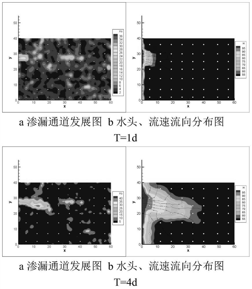
[0109] The mean value, variance and relative scale of the internal structure of the embankment are specified, and the piping development process is simulated through multi-source response data. Set the simulation step size to 1 day, and display the devel...


PUM


Abstract

The invention discloses a pipeline development prediction and early warning method based on dynamic tomographic scanning, comprising the following steps: interpreting the progressive erosion mechanism of aquifers and the dynamic response law of seepage field; establishing a fluid-solid coupling model of progressive erosion of aquifers; arranging monitoring wells to collect data Monitoring data; establishing a multi-source monitoring data interpretation model for progressive erosion of aquifers; calculating the current seepage field; calculating the erosion situation with the piping fluid-solid coupling model; updating the seepage field and iteratively calculated to the step size requirement. The method of the invention combines the characteristics of the piping fluid-solid coupling model and the advantages of the hydraulic tomography scanning to characterize the heterogeneous aquifer, and predicts the dynamic development of the piping channel. Real-time feedback and precise positioning have been greatly improved.

Description

technical field [0001] The invention relates to the field of stratum lithology and geological structure geophysical exploration, in particular to a piping development prediction and early warning method based on dynamic tomographic scanning. Background technique [0002] Seepage damage generally refers to the process of particle loss and further damage caused by seepage inside or at the bottom of the dam. 46.1% of dyke failures in the world are caused by seepage failure. According to the latest classification, seepage damage can be divided into four types: concentrated leakage erosion, contact erosion, subsurface erosion, and reverse erosion piping. Reverse erosion piping is the main reason for the failure of embankment instability. Historically, major embankments in my country, including the Jingjiang Embankment, the Beijiang Embankment, and the Huaihe Embankment, have all been damaged due to piping. Especially in the middle and lower reaches of the Yangtze River, the sp...

Claims


Application Information

Patent Timeline
Patent Type & Authority Patents(China)
IPC IPC(8): G06F30/20G06F17/11G06F17/16G01N27/62G01N15/08G06F111/10G06F113/08G06F119/14
CPCG06F30/20G06F17/11G06F17/16G01N27/62G01N15/08G06F2111/10G06F2113/08G06F2119/14
Inventor 梁越夏日风叶天齐张宏杰孙志伟汪魁赵明阶徐炜陈晴空邢冰张静
Owner CHONGQING JIAOTONG UNIVERSITY
Why Eureka
Try Eureka