Bridge structure temperature field monitoring method

A bridge structure and temperature field technology, applied in the field of bridge structures, can solve problems such as high cost, decreased accuracy, and inability to feed back data from sensors, and achieve the effects of low cost, wide monitoring range, and convenient installation and use

Pending Publication Date: 2020-09-29
中电建路桥集团有限公司
View PDF0 Cites 8 Cited by
  • Summary
  • Abstract
  • Description
  • Claims
  • Application Information

AI Technical Summary

Problems solved by technology

This method has three disadvantages: first, the cost of the required sensors and data acquisition and transmission equipment is high, and a large amount of manpower and material resources are required for installation and commissioning; second, only the temperature data of limited positions of the bridge can be obtained, and the temperature of the whole bridge cannot be grasped. Third, the life of the sensor is limited, the surface sensor needs to be replaced regularly, and the embedded sensor cannot feedback data after a few years
However, the coefficients in the theoretical calculation model need to rely on a large amount of measured data and related data statistics experience. If it is used to simulate the temperature field, there are three shortcomings: First, the solar radiation calculation model is only suitable for sunny days, not for all weathers H

Method used


Image

  • Bridge structure temperature field monitoring method
  • Bridge structure temperature field monitoring method
  • Bridge structure temperature field monitoring method

Examples


Embodiment Construction

[0065] Embodiments of the present invention will be further described below in conjunction with the accompanying drawings.

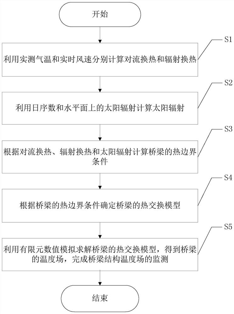
[0066] Such as figure 1 As shown, the invention provides a bridge structure temperature field monitoring method, comprising the following steps:

[0067] S1: Use the measured air temperature and real-time wind speed to calculate the convective heat transfer and radiation heat transfer respectively;

[0068] S2: Calculate the solar radiation using the daily ordinal number and the solar radiation on the horizontal plane;

[0069] S3: Calculate the thermal boundary conditions of the bridge based on convective heat transfer, radiation heat transfer and solar radiation;

[0070] S4: Determine the heat exchange model of the bridge according to the thermal boundary conditions of the bridge;

[0071] S5: Use finite element numerical simulation to solve the heat exchange model of the bridge, obtain the temperature field of the bridge, and complete the monitori...


PUM


Abstract

The invention discloses a bridge structure temperature field monitoring method. The method comprises the following steps: S1, respectively calculating convective heat transfer and radiant heat transfer by utilizing an actually measured air temperature and a real-time air speed; S2, calculating solar radiation by utilizing the daily ordinal number and the solar radiation on the horizontal plane; S3, calculating a thermal boundary condition of the bridge according to the convective heat transfer, the radiant heat transfer and the solar radiation; S4, determining a heat exchange model of the bridge according to the thermal boundary condition of the bridge; and S5, solving the heat exchange model of the bridge by utilizing finite element numerical simulation to obtain a temperature field of the bridge, and completing monitoring of the temperature field of the bridge structure. The method does not need to depend too much on actually measured temperature data, only needs to install meteorological stations including temperature sensors, wind speed sensors and a total radiometer at a bridge site, and suggests that a few temperature sensors are installed on a bridge and model parameters areadjusted during initial use; cost is low and installation and usage are convenient; the monitoring range is wide, and full-bridge temperature monitoring can be realized.

Description

technical field [0001] The invention belongs to the technical field of bridge structures, and in particular relates to a method for monitoring the temperature field of a bridge structure. Background technique [0002] Under the effect of temperature difference under sunlight, due to the poor thermal conductivity of concrete itself, the external temperature rises rapidly, while the internal temperature remains basically unchanged, and the temperature field of the bridge presents obvious nonlinear distribution characteristics. For bridges with high concrete piers, the nonlinear temperature difference of hollow high piers will cause bridge deformation, which has a non-negligible impact on the static state and dynamic characteristics of the bridge. With the development of my country's transportation industry, the road network construction in Southwest China has been continuously improved, and more and more concrete high-pier bridges across mountain canyons have begun to be const...

Claims


Application Information

Patent Timeline
IPC IPC(8): G06F30/23G06F119/08
CPCG06F30/23G06F2119/08
Inventor 陈钒艾祖斌侯圣均王超
Owner 中电建路桥集团有限公司
Why Eureka
Try Eureka